The Steam-Engine of Today
. . . And, last of all, with inimitable power, and 'with whirlwind sound,' comes the potent agency of steam. In comparison with the past, what centuries of improvement has this single agent comprised in the short compass of fifty years ! Everywhere practicable, everywhere efficient, it has an arm a thousand times stronger than that of Hercules, and to which human ingenuity is capable of fitting a thousand times as many hands as belonged to Briareus. Steam is found in triumphant operation on the seas; and, under the influence of its strong propulsion, the gallant ship
'Against the wind, against the tide,
Still steadies with an upright keel.'
It is on the rivers, and the boatman may repose on his oars; it is on highways, and exerts itself along the courses of and conveyance; it is at the bottom of mines, a thousand feet below the earth's surface; it is in the mills, and in the workshops of the trades. It rows, it pumps, it excavates, it carries, it draws, it lifts, it hammers, it spins, it weaves, it prints. It seems to say to men, at least to the class of artisans: 'Leave off your manual labor; give over your bodily toil; bestow but your skill and reason to the directing of my power, and I will bear the toil, with no muscle to grow weary, no nerve to relax, no beast to feel faintness!' What further improvement may still be made in the use of this astonishing power it is impossible to know, and it were vain to conjecture. What we do know is, that it has most essentially altered the face of affairs, and that no visible limit yet appears beyond which its progress is seen to be impossible." DANIEL WEBSTER,
THE PERIOD OF REFINEMENT1850 TO DATE.
BY the middle of the present century, as we have now seen, the steam-engine had been applied, and successfully, to every great purpose for which it was fitted. Its first application was to the elevation of water; it next was applied to the driving of mills and machinery; and it finally became the great propelling power in transportation by land and by sea.
At the beginning of the period to which we are now come, these applications of steam-power had become familiar both to the engineer and to the public. The forms of engine adapted to each purpose had been determined, and had become usually standard. Every type of the modern steam-engine had assumed, more or less closely, the form and proportions which are now familiar; and the most intelligent designers and builders had been taught by experience rather than by theory, for the theory of the steam engine had then been but little investigated, and the principles and laws of thermodynamics had not been traced in their application to this engine the principles of construction essential to successful practice, and were gradually learning the relative standing of the many forms of steam-engine, from among which have been preserved a few specially fitted for certain specific methods of utilization of power.
During the years succeeding the date 1850, therefore, the growth of the steam-engine had been, not a change of standard type, or the addition of new parts, but a gradual improvement in forms, proportions, and arrangements of details; and this period has been marked by the dying out of the forms of engine least fitted to succeed in competition with others, and the retention of the latter has been an example of "the survival of the fittest. "This has therefore been a Period of Refinement.
During this period invention has been confined to details; it has produced new forms of parts, new arrangements of details; it has devised an immense variety of valves, valve-motions, regulating apparatus, and a still greater variety of steam-boilers and of attachments, essential and non-essential, to both engines and boilers. The great majority of these peculiar devices have been of no value, and very many of the best of them have been found to have about equal value. All the well-known and successful forms of engine, when equally well designed and constructed and equally well managed, are of very nearly equal efficiency; all of the best-known types of steam boiler, where given equal proportions of grate to heating-surface and equally well designed, with a view to securing a good draught and a good circulation of water, have been found to give very nearly equally good results; and it has become evident that a good knowledge of principles and of practice, on the part of the designer, the constructor, and the manager of the boiler, is essential in the endeavor to achieve economical success; that good engineering is demanded, rather than great ingenuity. The inventor has been superseded here by the engineer.
The knowledge acquired in the time of Watt, of the essential principles of steam-engine construction, has since become generally familiar to the better class of engineers. It has led to the selection of simple, strong, and durable forms of engine and boiler, to the introduction of various kinds of valves and of valve-gearing, capable of adjustment to any desired range of expansive working, and to the attachment of efficient forms of governor to regulate the speed of the engine, by determining automatically the point of cutoff which will, at any instant, best adjust the energy exerted by the expanding steam to the demand made by the work to be done.
The value of high pressures and considerable expansion was reorganized as long ago as in the early part of the present century, and Watt, by combining skillfully the several principal parts of the steam-engine, gave it very nearly the shape which it has to-day. The compound engine, even, as has been seen, was invented by contemporaries of Watt, and the only important modifications since his time have occurred in details. The introduction of the " drop cut-off," the attachment of the governor to the expansion apparatus in such a manner as to determine the degree of expansion, the improvement of proportions, the introduction of higher steam and greater expansion, the improvement of the marine engine by the adoption of surface-condensation, in addition to these other changes, and the introduction of the double-cylinder engine, after the elevation of steam-pressure and increase of expansion had gone so far as to justify its use, are the changes, therefore, which have taken place during this last quarter-century. It began then to be generally understood that expansion of steam produced economy, and mechanics and inventors vied with each other in the effort to obtain a form of valve-gear which should secure the immense saving which an abstract consideration of the expansion of gases according to Marriotte's law would seem to promise. The counteracting phenomena of internal condensation and reevaporation, of the losses of heat externally and internally, and of the effect of defective vacuum, defective distribution of steam, and of back-pressure, were either unobserved or were entirely overlooked.
It was many years, therefore, before engine-builders became convinced that no improvement upon existing forms of expansion-gear could secure evenan approximation to theoretical efficiency.
The fact thus learned, that the benefit of expansive working has a limit which is very soon reached in ordinary practice, was not then, and has only recently become, generally known among our steam-engine builders, and for several years, during the period upon which we now enter, there continued the keenest competition between makers of rival forms of expansion-gear, and inventors were continually endeavoring to produce something which should far excel any previously-existing device.
In Europe, as in the United States, efforts to " improve " standarddesigns have usually resulted in injuring their efficiency, and in simplyadding to the first cost and running expense of the engines, without securinga marked increase in economy in the consumption of steam.
SECTION I. STATIONARY ENGINES.
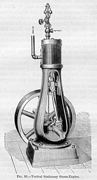
"STATIONARY ENGINES had been applied to the operation of mill-machinery,as has been seen, by Watt and by Murdoch, his assistant and pupil; andWatt's competitors, in Great Britain and abroad, had made considerableprogress before the death of the great engineer, in its adaptation to itswork. In the United States, Oliver Evans had introduced the non-condensinghigh pressure stationary engine, which was the progenitor of the standardengine of that type which is now used for more generally than any otherform. These engines were at first rude in design, badly proportioned, roughand inaccurate as to workmanship, and uneconomical in their consumptionof fuel. Gradua11y, however, when made by reputable builders, they assumedneat and strong shapes, good proportions, and were well made and of excellentmaterials, doing their work with comparatively little waste of heat orof fuel. One of the neatest and best modern designs of stationary enginefor small powels is seen in Fig. 93, which represents a " verticaldirect-acting engine," with baseplate a form which is a favoritewith many engineers. The engine shown in the engraving consists of twoprincipal parts, the cylinder and the frame, which is a tapering columnhaving openings in the sides, to allow free access to all the working partswithin. The slides and pillowblocks are cast with the column, so that theycannot become loose or out of line; the rubbing surfaces are large andeasily lubricated. Owing to the vertical position, there is no tendeneyto side wear of cylinder or piston. The packing-rings are self-adjusting,and work free but tight. The crank is counterbalanecd; the crank-pin, cross-headpin, piston-rod, va1ve-stem, etc., are made of steel; all the bearing surfacesare made extra large, and are accurately fitted; and the best qua1ity ofBabbitt-metal only used for the journal-bearings. The smaller sizes ofthese engines, from 2 to l0 horsepower, have both pillow-blocks cast inthe frame, giving a

Fig. 93. Vertical Stationary Steam-Engine.
bearing each side of the double cranks. They are built by some constructorsin quantities, and parts duplicated by special machinery (as in fire-armsand sewing-machines), which secures great accuracy and uniformity of workmanship,and allows of any part being quickly and cheaply replaced, when worn orbroken by accident. The next figure is a vertical section through the sameengine.
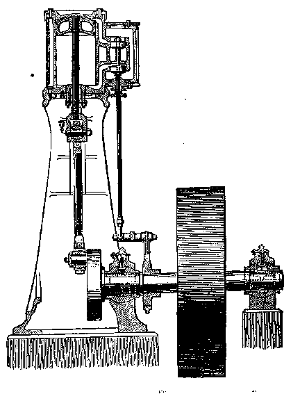
Fig. 94. Vertical Stationary Steam-Engine. Section.
Engines fitted with the ordinary rigid bearings require to be erectedon a firm foundation, and to be kept in perfcet line. If, by the settlingof the foundation, or from any other cause, they get out of line, heating,cutting, and thumping result. To obviate this, modern engines are oftenfitted with self-adjusting bearings throughout; this gives the engine greatflexibility and freedom from friction. The accompanying cuts show clearlyhow this is accomplished. The pillow-block has a spherical shell turnedand fitted into the spherically-bored pillow-block, thus allowing a slightangular motion in any direction. The connecting-rod is forged in a singlepiece, without straps, gibs, or key, and is mortised through at each endfor the reception of the brass boxes, which are curved on their backs,and fit the cheek-pieces, between which they can turn to adjust themselvesto the pins, in the plane of the axis of the rod. The adjustment for wearis made by wedge-blocks and set screws, as shown, and they are so constructedthat the parts cannot get loose and cause a break-down. The crosshcadhas adjustable gibs on each side, turned to fit the slides, which are eastsolidly in the frame, and bored out exactly in the line with the cylinder.This permits it freely to turn on its axis, and, in connection with theadjustable boxes in the connecting-rod, allows a perfect self-adjustmentto the line of the crank-pin. The out-board bearing may be moved an inchor more out of position in any direction, without detriment to the runningof the engine, all bearings accommodating themselves perfectly to whateverposition the shaft may assume.
The ports and valve-passages are proportioned as in locomotive practice.The valve-seat is adapted to the ordinary plain slide or D-valve, shouldit be preferred, but the ba1anecd piston slide-valve works with equal casewhether the steam-pressure is 10 or l00 pounds, and at the same time givesdouble steam and exhaust openings, which greatly facilitates the entranceof the steam to, and its escape from, the cylinder, thus securing a nearerapproach to boiler-pressure and a less back-pressure, saving the powerrequired to work an ordinary valve, and reducing the wear of valve-gear.
This is a type of engine frequently scen in the United States, but morerarely in Europe. It is an excellent form of engine. The vertical direct-actingengine is sometimes, though rarely, built of very considerable size, andthese large engines are more frequently seen in rolling-mills than elsewhere.
Where much power is required, the stationary engine is usually an horizontaldirect-acting engine, having a more or less effcetive cut-off valve-gear,according to the size of engine and the cost of fuel. A good example ofthe simpler form of this kind of engine is the small horizontal slidevalveengine, with independent cut-off valve riding on the back of the main valve acombination generally known among engineers as the Meyer system of valve-gear.This form of steam-engine is a very effective machine, and does excellentwork when properly proportioned to yield the required amount of power.It is well adapted to an expansion of from four to five times. Its disadvantagesare the difficulty which it presents in the attachment of the regulator,to determine the point of cut-off by the heavy work which it throws uponthe governor when attached, and the rather inflexible character of thedevice as an expansive valve-gear. The best cxamples of this class ofengine have neat heavy bed-plates, well-designed cylinders and details,smooth-working valve-gear, the expansion-valve adjusted by a right andleft hand screw, and regulation secured by the attachment of the governorto the throttle-valve.
The engine shown in the accompanying illustration (Fig. 95) is an exampleof an excellent British stationary steam-engine. It is simple, strong,and efficient. The frame, front cylinder-head, cross-head guides, and crankshaft" plumberblock," are cast in one piece, as has so generallybeen done in the United States for a long time by some of our manufacturers.The cylinder is secured against the end of the bed-plate, as was firstdone by Corliss. The crank-pin is set in a counterbalanced disk. The valve-gearis simple, and the governor effective, and provided with a safety-deviceto prevent injury by the breaking of the governor-belt. An engine of thiskind of 10 inchcs diameter of cylinder, 20 inches stroke of piston, israted by the builders at about 25 horse-power; a similar engine 30 inchcsin diameter of cylinder would yield from
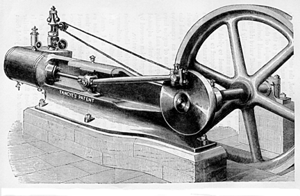
Fig. 95. - Horizontal Stationary Steam-Engine.
225 to 250 horse-power. In this example, all parts are made to exactsize by gauges standardized to Whitworth's sizes.
In American engines (as is seen in Fig. 96), usually, two supports areplaced the one under the latter bearing, and

Fig. 96. - Horizontal Stationary Steam-Engine.
the other under the cylinder to take the weight of the engine; andthrough them it is secured to the foundation. As in the vertical enginealready described, a valve is sometimes used, consisting of two pistonsconnected by a rod, and worked by an ordillary eccentric. By a simple arrangementthese pistons have always the same pressure inside as out, which preventsany leakage or blowing through; and they are said always to workequallyas well and free from friction under 150 pounds pressure as under 10 poundsper square ineh, and to require no adjustment. It is more usual, however,to adopt the three-ported valve used on locomotives, with (frequently)a cut-off valve on the back of this main valve, which cut-off valve isadjusted either by hand or by the governor.
Engines of the class just described are especially well fitted, by theirsimplicity, compactness, and solidity, to work at the high piston-speedswhich are gradually becoming generally adopted in the effort to attainincreased economy of fuel by the reduetion of the immense losses ofheatwhich occur in the expansion of steam in the metallic cylinders throughwhich we are now compelled to work it.
One of the best known of recent engines is the Allen engine, a steam-enginehaving the same general arrangement of parts seen in the above illustration,but fitted with a peculiar valve-gear, and having proportions of partswhich are especially calculated to secure smoothness of motion and uniformityof pressure on crank-pin and journals, at speeds so high that the inertiaof the reciprocating parts becomes a seriously-important element in thecalculation of the distribution of stresses and their effect on the dynamicsof the machine.
In the Allen engine,1 the cylinder and frame are connected as in the engineseen above, and the crank-disk, shaft-bearings, and other principal details,are not essentially different. The valve-gear2 differs in having four valves,one at each end on the steam as well as on the exhaust side, all of whichare balanced and work with very little resistance. These valves are notdetachable, but are driven by
1 The invention of Messrs. Charles T. Porter and JohnF. Allen
2 Invented by Mr. John F. Allen
a link attached to and moved by an eccentric on the main shaft, theposition of the valve-rod attachment to which link is determined by thegovernor, and the degree of expansion is thus adjusted to the work of theengine. The engine has usually a short stroke, not exceeding twice thediameter of cylinder, and is driven at very high speed, generally averagingfrom 600 to 800 feet per minute.(1) This high piston-speed and short strokegive very great velocity of rotation. The effeet is, therefore, to producean exceptional smoothness of motion, while permitting the use of smallfly-wheels. Its short stroke enables entire solidity to be attained ina bed of rigid form, making it a very completely self-eontained engine,adapted to the heaviest work, and requiring only a small foundation.
The journals of the shaft, and all cylindrieal wearing surfaces, are finishedby grinding in a manner that leaves them perfectly round. The crank-pinand cross-head pin are hardened before being ground. The joints of thevalve gear consist of pins turning in solid ferrules in the rod-ends, bothhardened and ground. After years of constant use thus, no wear occasioninglost time in the valve-movements has been detected.
High speed and short strokes are essential elements of economy. It is nowwell understood that all the surfaecs with which the steam comes in contactcondense it.
Obviously, one way to diminish this loss is to reduce the extent of surfaceto which the steam is exposed. In engines of high speed and short stroke,the surfaces with which the steam comes in contact, while doing a givenamount of work, present less area than in ordinary engines running at lowspeed. Where great steadiness of motion is desired, the expense of coupledengines is often incurred. Qnick-running engines do not require to be coupled;a single engine may give greater uniformity of motion than is usually obtainedwith coupled engines at ordinary speeds. The ports and valve-movements,the weight of the reciprocating parts, and the size and weight of the fly-wheels,should be calculated expressly for the speeds chosen. The economy of theengine here described is unexcelled by the best of the more familiar "drop cut-off" engines.
An engine reported upon by a committee of the American Institute, of whichDr. Barnard was chairman, was non-condensing, 16 inehes in diameter ofcylinder, 30 inches stroke, making 125 revolutions per minute, and developedover 125 horse-power with 75 pounds of steam in the boiler, using 254 poundsof steam per indicated horse-power, and 2.87 pounds of coal an extraordinarilygood performance for an engine of such small power.
The governor used on this engine is known as the Porter governor. It isgiven great power and delicacy by weighting it down, and thus obtaininga high velocity of rotation, and by suspending the balls from forked arms,which are given each two bearing-pins separated laterally so far as topermit considerable force to be exerted in charging speeds without crampingthose bearings suffieiently to seriously impair the sensitiveness of thegovernor. This engine as a whole may be regarded as a good representativeof the high-speed engine of to-day.
Since this change in the direction of high speeds has already gone so farthat the " drop cut-off " is sometimes inapplicable, in consequenceof the fact that the piston would, were such a valve-gear adopted, reachthe end of its stroke before the detached valve could reach its seat; andsince this progress is only limited by our attainments in mechanical skilland accuracy, it seems probable that the "positive-motion expansion-gear"type of engine will ultimately supersede the now standard " drop cut-offengine."
The best known and most generally used class of stationary engines at thepresent time is, however, that which
1 Or not far from 600 times the cube root of the lengthof stroke, measured in feet.
has the so-called " drop cut-off," or " detachable valve-gear."
The oldest well-known form of valvemotion of this description now inuse is that known as the Sickels cut-off, patented by Frederick E. Sickels,an American mechanic, about the year 1841, and also built by Hogg, of NewYork, who placed it upon the engine of the steamer South America. Theinvention is claimed for both Hogg and Sickels. It was introduced by theinventor in a form which especially adapted it to use w ith the beam-engineused on the Eastern waters of the United States, and was adapted to stationaryengines by Messrs. Thurston, Greene & Co., of Providence, R. I., whomade use of it for some years before any other form of "drop cut-off"came into general use.
The Sickels cut-off consisted of a set of steam-valves, usually independentof the exhaust-valves, and each raised by a catch, which could be thrownout, at the proper moment, by a wedge with which it came in contact asit rose with the opening valve. This wedge, or other equivalent device,was so adjusted that the valve should be detached and fall to its seatwhen the piston reached that point in its movement, after taking steam,at which expansion was to commence.
From this point, no steam entering the cylinder, the piston was impelledby the expanding vapor. The valve was usually the double-poppet. Sickelssubsequently invented what was called the " beam-motion," todetach the valve at any point in the stroke. As at first arranged, thevalve could only be detached during the earlier half-stroke, since at mid-strokethe direction of motion of the eccentric rod was reversed and the valvebegan to descend. By introducing a "wiper" having a motion transverseto that of the valve and its catch, and by giving this with a notion coincidentwith that of the piston by connecting it with the beam or other part ofthe engine moving with the piston, he obtained a kinematic combinationwhich permitted the valve to be detached at any point in the stroke, addinga very simple contrivance which enabled the attendant to set the wiperso that it should strike the catch at any time during the forward movementof the "beam-motion."
On stationary engines, the point of cut-off was afterward determined bythe governor, which was made to operate the detaching mechanism, the combinationforming what is sometimes called an " automatic " cut-off. Theattachment of the governor so as to determine the degree of expansion hadbeen proposed before Sickels's time. One of the earliest of these contrivanceswas that of Zachariah Allen, in 1834, using a cut-off valve independentof the steam-valve. The first to so attach the governor to a drop cut-offvalve-motion was George H. Corliss, who made it a feature of the Corlissvalve-gear in 1849. In the year 1855, N. T. Greene introduced a form ofexpansion-gear, in which the combined the range of the Sickels beam-motiondevice with the expansion-adjustment gained by the attachment of the governor,and with the advantages of flat slide-valves at all ports both steamand exhaust.
Many other ingenious forms of expansion valve-gear have been invented,and several have been introduced, which, properly designed and proportionedto well-planned engines, and with good construction and management, shouldgive economical results little if at all inferior to those just named.Among the most ingenious of these later devices is that of Babcock &Wilcox, in which a very small auxiliary steam-cylinder and piston is employedto throw the cut-off valve over its port at the instant at which the steamis to be cut off. A very beautiful form of isochronous governor is usedon this engine, to regulate the speed of the engine by determining thepoint of cut-off.
In Wright's engine, the expansion is adjusted by the movement, by the regulator,of cams which operate the steam-valves so that they shall hold the valveopen a longer or sholter time, as required.
Since compactness and lightness are not as essential as in portable, locomotive,and marine engines, the parts are arranged, in stationary engines, witha view simply to securing efficiency, and the design is determined by circumstances.It was formerly usual to adopt the condensing engine in mills, and wherevera stationary engine was required. In Europe generally, and to some extentin the United States, where a supply of condensing water is obtainable,condensing engines and moderate steam-pressures are still employed. Butthis type of engine is gradually becoming superseded by the high-pressurecondensing engine, with considerable expansion, and with all expansion-gearin which the point of cut-off is determined by the governor.
The best-known engine of this class is the Corliss engine, which is veryextensively used in the United States, and which has been copied very generallyby European builders. Fig. 97 represents the Corliss engine. The

Fig. 97. Corliss Engine.
horizontal steam-cylinder is bolted firmly to the end of the frame,which is so formed as to transmit the strain to the main journal with thegreatest directness. The frame carries the guides for the cross-head, whichare both in the same vertical plane. The valves are four in number, a steamand an exhaust valve being placed at each cnd of the steam-cylinder. Shortsteam-passages are thus secured, and this diminution of clearance is asourec of some economy. Both sets of valves are driven by an eccentricoperating a disk or wrist-platc, E (Fig. 98), which vibrates on a pin projectingfrom the cylinder. Short links reaching from this wrist-plate to the severalvalves, D D, F F, move them with

Fig. 98.-Corliss Engine Valve-Motion.
a peculiarly varying motion, opening and closing them rapidly, and movingthem quite slowly when the port is either nearly open or almost closed.This effect is ingeniously secured by so placing the pins on the wrist-platethat their line of motion becomes nearly transverse to the direction ofthe valve-links when the limit of movement is approached. The links connectingthe wrist-plate with the arms moving the steam-valves have catches attheir extremities, which are disengaged by coming in contact, as the armswings around with the valve-stem, with a cam adjusted by the governor.This adjustment permits the steam to follow the piston farther wllen theengine is called to " slow down," and thus tends to restore theproper speed. It disengages the steam-va1ve earlier, and expands the steamto a greater extent, when the engine begins to run above the proper speed.When the catch is thrown out, the valve is closed by a weight or a strongspring. To prevent jar when the motion of the valve is checked, a "dash-pot"is used, invented originally by F. E. Sickels. This is a vessel havinga nicely-fitted piston, which is received by a "cushion" of wateror air when the piston suddenly enters the cylinder at the end of the valve-movement.In the original water dashpot of Sickels, the cylinder is vertical, andthe plunger

Fig. 99. Greene Engine.
or piston descends upon a small body of water confined in the base ofthe dash-pot. Corliss's air dash-pot is now often set horizontally.
In the Greene steam-engine (Fig. 99), the valves are four in number, asin the Corliss. The cut-off gear consists of a bar, A, moved by the steam-eccentricin a direction parallel with the centre-line of the cylinder and nearlyco-incident as to time with the piston. On this bar are tappets, C C,supported by springs and adjustable in height by the governor, G. Thesetappets engage the arms B B, on the ends of rock-shafts, E E, which movethe steam-valves and remain in contact with them a longer or shorter time,and holding the valve open during a greater or less part of the piston-stroke,as the governor permits the tappets to rise with diminishing engine-speed,or forces them down as speed increases. The exhaust-valves are moved byan in dependent eccentric rod, which is itself moved by an eccentric
Fig. 100.-The Green Engine.
set, as is usual with the Corliss and with other engines generally,at right angles with the crank. This engine, in consequence of the independenceof the steam-eccentric, and of the contemporary movement of steam valve-motionand steam-piston, is capable of cutting off at any point from beginningto nearly the end of the stroke. The usual arrangement, by which steamand exhaust valves are moved by the same eccentric, only permits expansionwith the range from the beginning to half-stroke. In the Corliss enginethe latter construction is retained, with the object, in part, of securinga means of closing the valve by a " positive motion," should,by any accident, the closing not be effected by the weight or spring usuallyrelied upon.
The steam-valve of the Greene engine, as designed by the anthor, is seenin Fig. l00, where the valve, G H, covering the port, D, in the steam-cylinder,A B, is moved by the rod, J J, connected to the rock-shaft, M, by the arm,L K. The line, K I, should, when carried out, intersect the valve-faceat its middle point, under G.
The characteristics of the American stationary engine, therefore, are highsteam-pressure without condensation, an expansion valve-gear with dropcut-off adjustable by the governor, high piston-speed, and lightness combinedwith strength of construction. The pressure most cormnonly adopted in theboilers which furnish steam to this type of engine is from 75 to 80 poundsper square inch; but a pressure of 100 pounds is not infrequently carried,and the latter pressule may be regarded as a "mean maximum,~ correspondingto a pressure of 60 pounds at about the commencement of the period hereconsidered.
Very much greater pressures have, however, been adopted by some makers,and immensely "higher steam" has been experimented with by severalengineers. As early as 1823, Jacob Perkins1 commenced experimenting withsteam of very great tension. As has already been stated, the usual pressureat the time of Watt was but a few pounds-5 or 7 in exeess of that ofthe atmosphere. Evans, Trevithick, and Stevens, had previously worked steamat pressures of from 50 to 75 pounds per square inch, and pressures onthe Western rivers and elsewhere in the United States had already beenraised to l00 or 150 pounds, and explosions were becoming alarmingly frequent.
Perkins's experimental apparatus consisted of a copper boiler, of a capacityof about one cubic foot, having sides 3, inches in thickness. It was closedat the bottom and top, and had five small pipes leading from the upperhead.
Perkins was a native of Newburyport, Mass. He was born July 9, 1766,and died in London, July 30, 1849. He went to England when fifty-two yearsof age, to introduce his inventions.
This was placed in a furnace kept at a high temperature by a forcedcombustion. Safety-valves loaded respectively to 425 and 550 pounds persquare inch were placed on each of two of the steam-pipes.
Perkins used the steam generated under these great pressures in a littleengine having a piston 2 inches in diameter and a stroke of 1 foot. Itwas rated at l0 horse-power. (l )
In the year 1827, Perkills had attained working pressures, in a single-acting,single-cylinder engine, of upward of 800 pounds per square inch. At pressuresexeeeding 200 pounds, he had much trouble in securing effective lubrication,as all oils charred and decomposed at the high temperatures then unavoidablyencountered, and he finally succceded in evading this seemingly insurmountableobstacle by using for rubbing parts a peculiar alloy which required nolubrication, and which beeame so beautifully polished, after some wear,that the friction was less than where lubricants were used. At these highpressures Perkins seems to have met with no other serious difficulty. Hecondensed the exhaust-steam and returned it to the boiler, but did notattempt to create a vacuum in his condenser, and therefore needed no air-pump.Steam Awas cut off at one-eighth stroke.
In the same year, Perkins made a compound engine on the Woolf plan, andadopted a pressure of 1,400 pounds, expanding. It was when writing of thisengine that Stuart wrote, in 1824: "Judging from the rapid stridesthe steam-engine has made during the last forty years to become a universalfirst-mover, and from the experience that has arisen from that extension,we feel convinced that every intention which diminishes its size withoutimpairing its power brings it a step nearer to the assistance of the 'world'sgreatest laborers,' the husbandman and the peasant, for whom, as yet, itperforms but little. At present, it is made occasionally to tread out thecorn. What honors await not that man who may yet direct its mighty powerto plough, to sow, to harrow, and to reap!" The progress of the steam-engineduring those forty years does not today appear so astounding. The sentimenthere expressed has lost none of its truth, nevertheless.
eight times. In still another engine, intended for a steam-vessel, Perkinsadopted, or proposed to adopt, 2,000 pounds pressure, cutting off the admissionat one-sixteenth, in single-acting engines of 6 inches diameter of cylinderand 20 inches stroke of piston. The steam did not retain boiler-pressureat the cylinder, and this engine was only rated at 30 horse-power.l
Stuart follows a description of Perkins's work in the improvement of thesteam-engine and the introduction of steam-artillery by the remark:
".... No other mechanic of the day has done more to illustrate anobscure branch of philosophy by a series of difficult, dangerous and expensiveexperiments; no one's labors have been more deserving of cheering encouragementand no one has received less. Even in their present state, his experimentsare opening new fields for philosophical researeh, and his mechanism bidsfair to introduce a new style into the proportions, construction, and formof steam-machinery. "
Perkins's experience was no exception to the general rule, which deniesto nearly all inventors a fair return for the benefits which they conferupon mankind.
Another engineer, a few years later, was also successful in controllingand working steam under much higher pressures than are even now in use.This was Dr. Ernst Alban, a distinguished German engine-builder, of Plau,Mecklenburg, and an admirer of Oliver Evans, in whose path he, a generationlater, advanecd far beyond that great pioneer. Writing in 1843, he describesa system of engine and hoiler construction, with which he used steam underpressures about equal to those experimentally worked by Jacob Perkins,Evans's American successor. Alban's treatise was translated and printedin Great Britain,2 four years later.
l Galloway and Hebert, on the Steam-Engine. London, 1836.
2 "The High-Pressure Steam-Engine,''etc. By Dr. Ernst Alban. Translatedby William Pole, F. R. A. S. London, 1847.
Alban, on one occasion, used steam of 1,000 pounds pressure. His boilerswere similar in general form to the boiler patented by Stevens in 1805,but the tubes were horizontal instead of vertical. He evaporated frorn8 to 10 pounds of water into steam of 600 to 800 pounds pressure with eachpound of coal. He states that the difficulty met by Perkins the decompositionof lubricants in the steam-cylinder did not present itself in his experiments,even when working steam at a pressurc of 600 pounds on the square inch,and he found that 1ess lubrication was needed at such high pressures thanin ordinary practice. Alban expanded his steam about as much as Evans,in his usual practice, carrying a pressure of 150 pounds, and cutting offat one-third; he adopted greatly increased piston-speed, attaining 300feet per minute, at a time when common practice had only reached 200 feet.He usually built an oscillating engine, and rarely attached a condenser.The valve was the locomotive-slide.l The stroke was made short to securestrength, compactness, cheapness, and high speed of rotation; but Albandoes not seem to have understood the principles controlling the form andproportions of the expansive engine, or the necessity of adopting considerableexpansion in order to secure economy in working steam of great tension,and therefore was, apparently, not aware of the advantages of a long strokein reducing losses by " dead space," in reducing risk of annoyanceby hot journals, or in enabling high piston-speeds to be adopted. He seemsnever to have attained a sufficiently high speed of piston to become awarethat the oscillating cylinder cannot be used at speeds perfectly practicablewith the fixed cylinder.
Alban states that one of his smallest engines, having a cylinder 45 inchesin diameter and 1 foot stroke of piston, with a piston-speed of but 140to l60 feet per minute, developed 4 horse-power, with a consumption of5.3 pounds
1 Invented by Joseph Maudsley, of London, 1827.
of coal per hour. This is a good result for so small an amount of work,and for an engine working at so low a speed of piston. An engine of 30horse-power, also working very slowly, required but 4.1 pounds of coalper hour.
The work of Perkins and of Alban, like that of their predecessors, Evans,Stevens, and Trevithick, was, however, the work of engineers who were farahead of their time. The general practice, up to the time which markedthe beginning of the modern " period of refinement," had beenbut gradua11y approximating that just described. Higher pressures wereslowly approached; higher piston speeds came slowly into use; greaterexpansion was gradually adopted; the causes of losses of heat were finallydiscovered, and steam-jacketing and external nonconducting coverings weremore and more generally applied as builders became more familiar with theirwork. The "compound engine" was now and then adopted; and eachexperiment, made with higher steam and greater expansion, was more nearlysuccessful than the last.
Finally, all these methods of securing economy became recognized, and thereasons for their adoption became known. It then remained, as the finalstep in this progression, to combine all these requisites of economicalworking in a double-cylinder engine, steam-jacketed, well protected bynon-conducting coverings, working steam of high pressure, and with considerableexpansion at high piston-speed. This is now done by the best builders.
One of the best examples of this type of engine is that constructed bythe sons of Jacob Perkins, who continued the work of their father afterhis death. Their engines are single-acting, and the small or high-pressurecylinder is placed on the top of the larger or low-pressure cylinder. Thevalves are worked by rotating stems, and the loss of heat and burning ofpacking incident to the use of the common method are thus avoided. Thestuffing-boxes are placed at the end of long sleeves, closely surroundingthe vertical valve-stems also, and the water of condensation which collectsin these sleeves is an additional and thorough protection against excessivelyhigh temperature at the packing. The piston-rings are made of the alloywhich has been found to require no lubrication.
Steam is usually worked at 240 pounds pressure, and is generated in boilerscomposed of small tubes three inches in diameter and three-eighths of aninch thick, which are tested under a pressure of 2,500 pounds per squareinch. The safety-valve is usually loaded to 400 pounds. The boiler is fedwith distilled water, obtained principally by condensation of the exhaust-steam,any deficiency being made up by the addition of water from a distillingapparatus. Under these conditions, but 1.5 pounds of coal is consumcd perhour and per horse-power.
The PUMPING-ENGINE in use at the present time has passed through a seriesof changes not differing much from that which has been traced with thestationary mill-engine. The Cornish engine is still used to some extentfor supplying water to towns, and is retained at deep mines. The modernCornish engine differs very little from that of the time of Watt, exceptin the proportions of parts and the form of its details. Steam-pressuresare carried which were never reached during the preceding period, and,by careful adjustment of well-set and well-proportioned valves and gearing,the engine has been made to work rather more rapidly, and to do considerablymore work. It still remains, however; a large, costly, and awkward contrivance,requiring expensive foundations, and demanding exceptional care, skill,and experience in management. It is gradually going out of use. This engine,as now constructed by good builders, is shown in section in Fig. 101.
A comparison with the Watt engine of a century earlier will at once enableany one to appreeiate the extent to which changes may be made in perfectinga machine, even after it has become complete, so far as supplying it withall essential parts can complete it.
In the figure, A is the eylinder, taking steam from the boiler throughthe steam-passage, M. The steam is first admitted above the piston, B,driving it rapidly downward
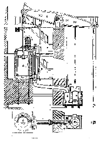
Fig. 101-Cornish Pumping-Engine, 1878. Section.
and raising the pump-rod, E. At an early period in the stroke the admissionof steam is checked by the sudden closing of the induction-valve at M,and the stroke is completed under the action of expanding steam assistedby the inertia of the heavy parts already in motion. The necessary weightand inertia is afforded, in many cases, where the engine is applied tothe pumping of deep mines, by the immensely long and heavy pump-rods. Whelethis weight is too great, it is counterbalanced, and where too small, weightsare added. When the stroke is completed, the " equilibrium valve "is opened, and the steam passes from above to the space below the piston,and an equilibrium of pressure being thus produced, the pump-lods descend,forcing the water from the pumps and raising the steam-piston. The absenceof the crank, or other device which might determine absolutely the lengthof stroke, compels a very careful adjustment of steam-admission to theamount of load. Should the stroke be allowed to exeeed the proper length,and should danger thus arise of the piston striking the cylinder-head,N, the movement is checked by buffer-beams. The valve-motion is actuatedby a plug-rod, J K, as in Watt's engine. The regulation is effected bya " cataract," a kind of hydraulic governor, consisting of aplunger-pump, with a reservoir attached. The plunger is raised by the engine,and then automatically detached. It falls with greatcr or less rapidity,its velocity being determined by the size of the eduction-orifice, whichis adjustable by hand. When the plunger reaches the bottom of the pump-barrel,it disengages a cateh, a weight is allowed to act upon the steam-valve,opening it, and the engine is caused to make a stroke. When the outletof the cataract is nearly closed, the engine stands still a considerabletime while the plunger is descending, and the strokes succeed each otherat long intervals. When the opening is greater, the cataract acts morerapidly, and the engine works faster. This has been regarded until recentlyas the most economical of pumping-engines, and it is still generally usedin freeing mines of water, and in situations where existing heavy pump-rodsmay be utilized in counterbalancing the steam-pressure, and, by their inertia,in continuing the motion after the steam, by its expansion, has becomegreatly reduced in pressure.
In this engine a gracefully-shaped and strong beam, D, has taken the placeof the ruder beam of the earlier period, and is carried on a well-builtwall of masonry, R. F is the exhaust-valve, by which the beam passes tothe condenser, G, beside which is the air-pump, H, and the hot-well, I.The cylinder is steam-jacketed, P, and protected against losses of heatby radiation by a brick wall, O, the whole resting on a heavy foundation,Q.
The Bull Cornish engine is also still not infrequently seen in use. TheCornish engine of Great Britain averages a duty of about 45,000,000 poundsraised one foot high per l00 pounds of coal. More than double this economyhas sometimes been attained.
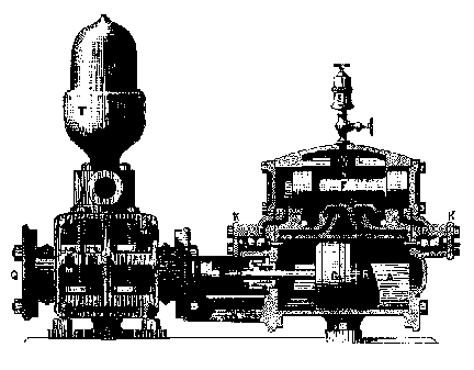
Fig. 102.-Steam-Pump.
A vastly simpler form of pumping-engine without flywheel is the nowcommon "direct-acting steam-pump." This engine is generally madeuse of in feeding steamboilers, as a forcing and fire pump, and whereverthe amount of water to be moved is not large, and where the pressure iscomparatively great. The steam-cylinder, A R, and feed-pump, B Q (Fig.l02), are in line, and the two pistons have usually one rod, D, in common.The two cylinders are connected by a strong frame, N and two standardsfitted with lugs carry the whole, and serve as a means of bolting the pumpto the floor or to its foundation.
The method of working the steam-valve of the modern steam-pump is ingeniousand peculiar. As shown, the pistons are moving toward the left; when theyreach the end of their stroke, the face of the piston strikes a pin orother contrivance, and thus moves a small auxiliary valve, I, which opensa port, E, and causes steam to be admitted behind a piston, or permitssteam to be exhausted, as in the figure, from before the auxiliary piston,F, and the pressure within the main steam-chest then forces that pistonover, moving the main steam-valve, G, to which it is attached, admittingsteam to the left-hand side of the main piston, and exhausting on the right-handside, A. Thus the motion of the engine operates its own valves in sucha manner that it is never liable to stop working at the end of the stroke,notwithstanding the absence ot the crank and fly-wheel, or of independentmechanism, like the cataract of the Cornish engine. There is a very considerablevariety of pumps of this class, all differing in detail, but all presentingthe distinguishing feature of auxiliary valve and piston, and a connectionby which it and the main engine each works the valve of the other combination.
In some cases these pumps are made of considerable size, and are appliedto the elevation of water in situations to which the Cornish engine wasformerly considered exclusively applicable. The accompanying figure illustratessuch a pumping-engine, as built for supplying cities with water. This isa "compound" direct-acting pumping-engine. The cylinders, AB, are placed in line, working one pump, F: and operating their own air-pumps,D D, by a bell-crank lever, L H, conneeted to the pump-buckets by links,I K. Steam exhausted from the small cylinder, A, is further expanded inthe large cylinder, B, and thence goes to the
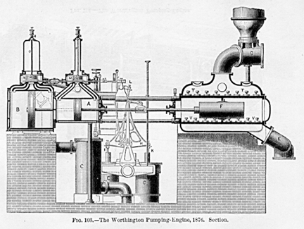
Fig. 103.-The Worthington Pumping-Engine, 1876. Section.
condenser, C. The valves, N M, are moved by the valve-gear, L, whichis actuated by the piston-rod of a similar pair of cylinders placed bythe side of the first. These valves are balanced, and the balance-plates,R Q, are suspended from the rods, O P, which allow them to move with thevalves. By connecting the valves of each engine with
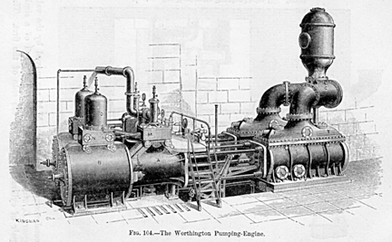
Fig. 104.-The Worthington Pumping-Engine.
the piston-rod of the other, it is seen that the two engines must workalternately, the one making a stroke while the other is still, and thenitself stopping a moment while the latter makes its stroke.
Water enters the pump through the induction-pipe, E, passes into the pump-barrelthrough the valves, V V, and issues through the eduction-valves, T T, andgoes on to the " mains " by the pipe, G, above which is seenan airchamber, which assists to preserve a uniform pressure on that sidethe pump. This engine works very smoothly and quietly, is cheap and durable,and has done excellent duty.
Beam pumping-engines are now almost invariably built with crank and fly-wheel,and very frequently are compound engines. The accompanying illustrationrepresents an engine of the latter form.
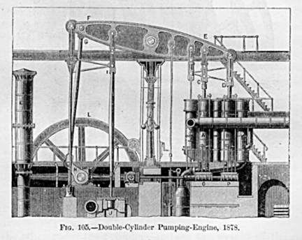
Fig. 105.-Double-Cylinder Pumping Engine, 1878.
A and B are the two steam-cylinders, connected by links and parallelmotion, C D, to the great cast-iron beam, E F. At the opposite end of thebeam, the connecting rod, G, turns a crank, H; and fly-wheel, L M, whichregulates the motion of the engine and controls the length of stroke, avertingall danger of accident occurring in consequence
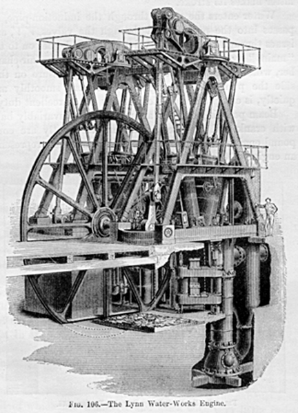
Fig. 106. The Lynn Water-Works Engine.
of the piston striking either cylinder-head. The beam is carried onhandsomely-shaped iron columns, which, with cylinders, pump, and fly-wheel,are supported by substantial stone foundation. The pump-rod, I, works adouble-acting pump, J, and the resistance to the issuing water is rendereduniform by an air-chamber, K, within which the water rises and falls whenpressures tend to vary greatly. A revolving shaft, N, driven from the fly-wheelshaft, carries cams, O P, which move the lifting-rods seen directly overthem and the valves which they actuate. Between the steam-cylinders andthe columns which carry the beams is a well, in which are placed the condenserand air
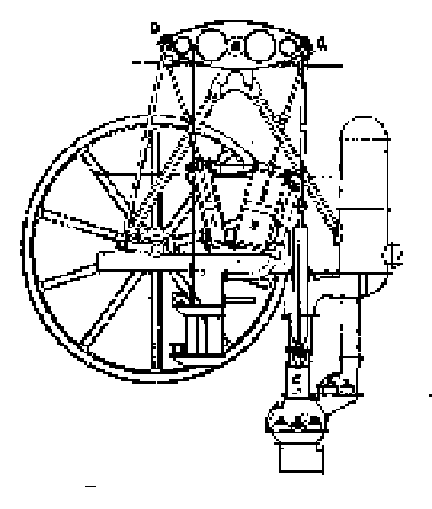
Fig. 107. The Leavitt Pumping-Engine.
pump. Steam is carried at 60 or 80 pounds pressure, and expanded from6 to 10 times.
A later form of double-cylinder beam pumping-engine is that invented anddesigned by E. D. Leavitt, Jr., for the Lynn (Mass.) Water-Works, and shownin Figs. 106 and 107. The two cylinders are placed one on each side thecentre of the beam, and are so inclined that they may be coupled to oppositeends of it, while their lower ends are placed close together. At theirupper ends a valve is placed at each end of the connecting steam-pipe.At their lower ends a singlc valve serves as cxhaust-valve to the high-pressureand as steam-valve to the low-pressure cylinder. The pistons move in oppositedirections, and steam is exhausted from the high-pressure cylinder directlyinto the nearer end of the low-pressure cylinder. The pump, of the "Thames-Ditton" or "bucket-and-plunger" variety, takes afull supply of water on the down-stroke, and discharges half when risingand half when descending again. The duty of this engine is reported bya board of engineers as 103,923,215 foot-pounds for every 100 pounds ofcoal burned. The duty of a moderately good engine is usually consideredto be from 60 to 70 millions. This engine has steam-cylinders of 17.5 and36 inches diameter respectively, with a stroke of 7 feet. The pump hada capacity of about 195 gallons, and delivered 96 per cent. Steam was carriedat a pressure of 75 pounds above the atmosphere, and was expanded about10 times. Plain horizontal tubular boilers were used, evaporating 8.58pounds of water from 98° Fahr. per pound of coal.
STEAM-BOILERS. Thc steam supplied to the forms of stationary enginewhich have been described is generated in steam-boilers of exceedinglyvaried forms. The type used is determined by the extent to which theircost is increased in the endeavor to economize fuel by the pressure ofsteam carried, by the greater or less neeessity of providing against riskof explosion, by thc character of the feed-water to be used, by the faciliticswhich may exist for keeping in good repair, and even by the character ofthe men in whose hands the apparatus is likely to be placed.
As has been seen, the changes which have marked the growth and developmentof the steam-engine have becn accompanied by equally marked changes inthe forms of the steam-boiler. At first, the same vessel served the distinct purposes of steam-generator and steam-engine. Later, it became separatedfrom the engine, and was then specially fitted to perform its own peculiarfunctions; and its form went through a series of modifications under theaction of the causes already stated.
When steam began to be usefully applied, and considerable pressuresbecame necessary, the forms given to boilers were approximately spherical,ellipsoidal, or cylindrical. Thus the boilers of De Caus (1615) and ofthe Marquis of Worcester (1663) were spherical and cylindrical; those ofSavery (1698) were ellipsoidal and cylindrical. After thc invention ofthe steam-engine of Newcomen, the pressures adopted were again very low,and steam-boilers were given irregular forms until, at the beginning ofthe present century, they were again of necessity given stronger shapes.The material was at first frequently copper; it is now usually wrought-iron,and sometimes steel.
The present forms of steam-boilers may be classified as plain, flue,and tubular boilers. The plain cylindrical or common cylinder boiler isthe only representative of the first class in common use. It is perfectlycylindrical, with heads either flat or hemispherical. There is usuallyattached to the boiler a "steam-drum" (a small cylindrical vessel),from which the steam is taken by the steam-pipe. This en largement of thesteam-space permits the mist, held in sus-pension by the steam when itfirst rises from the surface of the water, to separate more or less completelybefore the steam is taken from the boiler.
Flue-boilers are frequently cylindrical, and contain one or more cylindricalflues, which pass through from end to end, beneath the water-line, conductingthe furnace-gases, and affording a greater area of heating-surface thancan be obtained in the plain boiler. They are usually from 30 to 48 inchesin diameter, and one foot or less in length for each inch of diameter.Some are, however, made 100 feet and more in length. The boiler is madeof iron .25 to .5 of an inch in thickness, with hemispherical or carefullystayed flat heads, and without flues. The whole is placed in a brickworksetting. These boilers are used where fuel is inexpensive, where the costof repairing would be great, or where the feed-water is impure. A cylindricalboiler, having one flue traversing it longitudinally, is called a Cornishboiler, as it is generally supposed to have been first used in Cornwall.It was probably first invented by Oliver Evans in the United States, previousto 1786, at which time he had it in use. The flue has usually a diameter0.5 or 0.6 the diameter of the boiler. A boiler containing two longitudinalflues is called the Lancashire boiler. This form was also introduced byOliver Evans. The flues have one-third the diameter of the boiler. Severalflues of smaller diameter are often used, and when a still greater proportionalarea of heating-surface is required, tubes of from 1.25 inch to 4 or 5inches in diameter are substituted for flues. The flues are usually constructedby riveting sheets together, as in making the shell or outer portion. Theyare sometimes welded by British manufacturers, but rarely if ever in theUnited States. Tubes are always " lap-welded " in the processof rolling them. Small tabes were first used in the United States, about1785. In portable, locomotive, and marine steam-boilers, the fire mustbe built within the boiler itself, instead of (as in the above describedstationary boilers) in a furnace of brickwork exterior to the boiler. Theflame and gases from the furnace or fire-box in these kinds of boiler arenever led through brick passages en route to the chimney, as often in thepreceding case, but are invariably conducted through flues or tubes, orboth, to the smoke-stack. These boilers are also sometimes used as stationaryboilers. Fig. 108 reprcsents such a steam-boiler in section, as it is usuallyexhibited in working drawings. Provision is made to secure a good circulationof water in these boilers by means of the "baffle-plates," seenin the sketch, which compel the water to flow as indicated by the arrows.The tubes are frequently made of brass or of copper, to secure rapid transmissionof heat to the water, and thus to permit the use of a smaller area of heating-surface
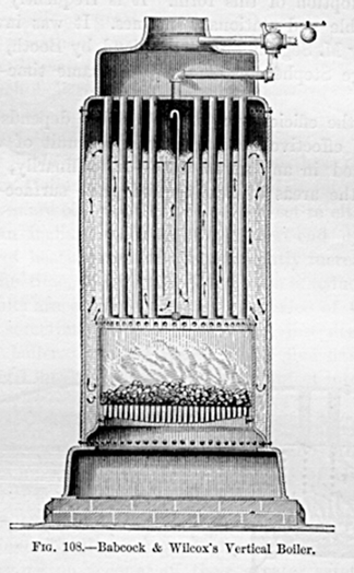
Fig. 108. Babcock & Wilcox's Vertical Boiler.
and a smaller boiler. The steam-space is made as large as possible,to secure immunity from " priming " or the " entrainment" of water with the steam. This type of steam-boiler, invented byNathan Read, of Salem, Mass., in 1791, and patented in April of that year,was the earliest of the tubular boilers. In the locomotive boiler (Fig.109), as in the preceding, the characteristics are a fire-box at one endof the shell and a set of tubes through which the gases pass directly tothe smoke-stack. Strength, compactness, great steaming capacity, fair economy,moderate cost, and convenicnce of combination with the running parts, aresecured by the adoption of this form. It is frequently used also for portableand stationary engines. It was invented in France by M. Seguin, and inEngland by Booth, and used by George Stephenson at about the same time 1828or 1829.
Since the efficiency of a steam-boiler depends upon the extent of effectiveheating-surface per unit of weight of fuel burned in any given time or,ordinarily, upon the ratio of the areas of heating and grate surface peculiar
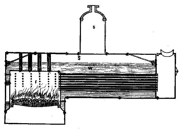
Fig. 109. Statlonary " Locomotive " Boiler.
expedients are sometimes adopted, having for their object the increaseof heating-surface, without change of form of boiler and without proportionateincrease of cost.
One of these methods is that of the use of Galloway conical tubes (Fig.110). These are very largely used in Great Britain, but are seldom if everseen in the United States. The Cornish boiler, to whieh they are usuallyapplied, consists of a large cylindrical shell, 6 feet or more in diameter,containing one tube of about one-half as great dimensions, or sometimestwo of one-third the diameter of the shell each. Such boilers have a verysmall ratio of heating to grate
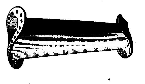
Fig. 110.
surface, and their large tubes are peculiarly liable to collapse. Toremove these objections, the Messrs. Galloway introduced stay-tubes intothe flues, which tubes are conical in form, and are set in either a verticalor an inclined position, the larger end uppermost. The area of heating-sulfaceis thus greatly increased, and, at the same time, the liability to collapseis reduced. The same results are obtained by another device of Galloway,which is sometimes combined with that just described in the same boiler.Several sheets in the flue have "pockets " worked into them,which pockets project into the flue-passage.
Another device is that of an American engineer, Miller, who surrounds thefurnace of cylindrical and other boilers with water-tubes. The "fuel-economizers"of Greene and others consist of similar collections of tubes set in theflues, between the boiler and the chimney.
"Sectional" boilers are gradually coming into use with high pressures,on account of their greater safety against disastrous explosions. The earliestpracticable example of a boiler of this class was probably that of ColonelJohn Stevens, of Hoboken, N. J. Dr. Alban, who, forty years later, attemptedto bring this type into general use, and constructed a number of such boilers,did not succeed. Their introduction, like that of all radical changes inengineering, has been but slow, and it has been only recently that theirmanufacture has become an important branch of industry.
A committee of the American Institute, of which the author was chairman,in 1871, examined several boilers of this and the ordinary type, and testedthem very carefully. They reported that they felt " confident thatthe introduction of this class of steam-boilers will do much toward theremoval of the cause of that universal feeling of distrust which rendersthe presence of a steam-boiler so objectionable in every locality. Thedifficulties in thoroughly inspecting these boilers, in regulating theiraction, and other faults of the class, are gradually being overcome, andthe committee look forward with confidence to the time when their use willbecome general, to the exclusion of older and more dangerous forms of steamboilers."
The economical performance of these boilers with a similar ratio of heatingto grate surface is equal to that of other kinds. In fact, they are usuallygiven a somewhat higher ratio, and their economy of fuel frequently exceedsthat of the other types. Their principal defect is their small capacityfor steam and water, which makes it extremely difficult to obtain steadysteam-pressure. Where they are employed, the feed and draught should be,if possible, controlled by automatic attachments, and the feedwater heatedto the highest attainable temperature. Their satisfactory working depends,more than in other cases, on the ability of the fireman, and can only besecured by the exercise of both care and skill.
Many forms of these boilers have been devised. Walter Hancock constructedboilers for his steam-carriage of flat plates connected by stay-bolts,several such sections composing the boiler; and about the same time (1828)Sir Goldworthy Gurney constructed for a similar purpose boilers consistingof a steam and a water reservoir, placed one above the other, and connectedby triangularly-bent watertubes exposed to the heat of the furnace-gases.Jacob Perkins made many experiments looking to the employment of very highsteam-pressures, and in 1831 patented a boiler of this class, in whichthe heating-surfaces nearest the fire were composed of iron tubes, whichtubes also served as gratebars. The steam and water space was principallycomprised within a comparatively large chamber, of which the walls weresecured by closely distributed stay-bolts. For extremely high pressures,boilers composed only of tubes were used. Dr. Ernst Allan described theboiler already referred to, and its construction and operation, and statedthat he had experimented with pressures as high as 1,000 pounds to thesquare inch.
The Harrison steam-boiler, which has been many years in use in the UnitedStates, consists of several sections, each of which is made up of hollowglobes of cast-iron, communicating with each other by necks east upon thespheres,
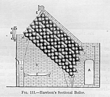
Fig. 111.-Harrison's Sectional Boiler.
and fitted together with faced joints. Long bolts, extending from endto end of each row, bind the spheres together. (See Fig. 111.)
An example of another modern type in extensive use is given in Fig. 112,a semi-sectional boiler, which consists of a series of inclined wrought-irontubes, connected by T-heads, which form the vertical water-channels, ateach end. The joints are faced by milling them, and then ground so perfectlytight that a pressure of 500 pounds to the square inch is insufficientto produce leakage. No packing is used.
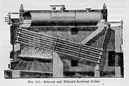
Fig. 112. Babcock and Wilcox's Sectional Boiler.
The fire is made under the front and higher end of the tubes, and theproducts of combustion pass up between the tubes into a combustion-chamberunder the steam and water drum; hence they pass down between the tubes,then once more up through the space between the tubes, and off to the chimney.The steam is taken out at the top of the steamdrum near the back end ofthe boiler. The rapid circulation prevents to some extent the formationof deposits or incrustations upon the heating-surfaces, sweeping them awayand depositing them in the mud-drum, whence they are blown out. Rapid circulationof water, as has been shown by Prof. Trowbridge, also assists in the extractionof the heat from the gases, by the presentation of fresh water continually,as well as by the prevention of incrustation.
Attempts have been made to adapt sectional boilers to marine engines; butvery little progress has yet been made
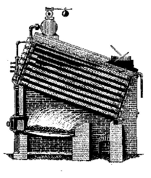
Fig. 113. Root Sectional Boiler.
in their introduction. The Root sectional boiler (Fig. 113), an Americandesign, which is in extensive use in the United States and Europe, hasalso been experimentally placed in service on shipboard. Its heating-surfaceconsists wholly of tubes, which are connected by a peculiarly formed seriesof caps; the joints are made tight with rubber " grommets."
SECTION II. PORTABLE AND LOCOMOTIVE ENGINES.
Engines and boilers, when of small size, are now often combined in onestructure which may be readily transported. Where they have a common base-platesimply, as in Fig. 114, they are called, usually, " semi-portableengines." These little engines have some decided advantages. Beingattached to one base, the combined engine and boiler is easily transported,occupies little space, and may very readily be mounted upon wheels, renderingit peculiarly well adapted for agricultural purposes.
The example here shown differs in its design from those usually seen inthe market. The engine is not fastened to or upon the boiler, and is thereforenot affected by expansion
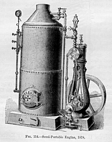
Fig. 114.-Semi-Portable Engine, 1878.
nor are the bearings overheated by conduction or by ascending heat fromthe boiler. The fly-wheel is at the base, which arrangement secures steadinessat the high speed which is a requisite for economy of fuel. The boilersare of the upright tubular style, with internal fire-box, and are intendedto be worked at 150 pounds pressure per inch. They are fitted with a baffle-plateand circulatingpipe, to prevent priming, and also with a fusible plug,which will melt and prevent the crown-sheet of the boiler burning, if thewater gets low.Another illustration of this form of engine, as built insmall sizes, is seen below. The peculiarity of this engine

Fig. 115. Semi-Portable Engine, 1878.
is, that the cylinder is placed in the top of the boiler, which is upright.By this arrangement the engine is constantly drawing from the boiler thehottest and driest steam, and there is thus no liability of serious lossby condensation, which is rapid, even in a short pipe, when the engineis separate from the boiler.
The engine illustrated is rated at 10 horse-power, and makers are alwaysexpected to guarantee their machines to work up to the rated power. Thecylinder is 7 by 7 inches, and the main shaft is directly over it. On thisshaft are three eccentrics, one working the pump, one moving the valves,and the third one operating the cut-off. the driving-pulley is 20 inchesin diameter and the balance-wheel 30 inches. The boiler has 15 1.25 inchflues. It is furnished with a heater in its lower portion. The boiler ofthis engine is tested up to 200 pounds, and is calculated to carry 100pounds working pressure, though that is not necessary to develop the fullpower of the engine. The compactness of the whole machine is exceptional.It can be set up in a space 5 feet square and 8 feet high. The weight ofthe 10 horse-power engine is 1,540 pounds, and of the whole machine 4,890pounds, boxed for shipment. Livery part of the mechanism usually fits andworks with the exactness of a gun-lock, as each piece is carefully madeto gauge.
Portable engines are those which are especially intended to be moved convenientlyfrom place to place. The engine is usually attached to the boiler and thefeed-pump is generally attached to the engine. The whole machine is carriedon wheels, and is moved from one place to another, usually by horses, butsometimes by its own engine, which is coupled by an engaging and disengagingapparatus to the rear-wheels. English builders have usually execlled inthe construction of this class of steam-engine, although it is probablethat the best Ameriean engines are fully equal to them in design, material,and construetion.
The later work of the best-known English builders has given economicalresults that have surprised engineers. The annual " shows " ofthe Royal Agricultural Society have elicited good evidence of skill inmanagement as well as of excellence of design and construction. Some littleportable engines have exhibited an economical efficiency superior to thatof the largest marine engines of any but the compound type, and even closelycompeting with that form. The causes of this remarkable economy are readilylearned by an inspection of these engines, and by observation of the methodof managing them at the test-trial. The engines are usually very carefullydesigned. The cylinders are nicely proportioned to their work, and theirpistons travel at high speed. Their valve-gear consists usually of a plainslide-valve, supplemented by a separate expansion-slide, driven by an independenteccentric, and capable of considerable variation in the point of cut-off.This form of expansion-gear is very effective almost as much so asa drop cut-off at the usual grade of expansion, which is not far fromfour times. The governor is usually attached to a throttle-valve in thesteam-pipe, an arrangement which is not the best possible under variableloads, but which produces no serious loss of effieicncy when the engineis driven, as at competitive trials, under the very uniform load of a Pronystrap-brake and at very nearly the maximum capacity of the machine. Themost successful engines have had steam-jacketed cylinders always anessential to maximum eeonomy with high steam and a considerable expansion.The boilers are strongly made, and are, as are also all other heated surfaces,carefully clothed with nonconducting material, and well lagged over all.The details are carefully proportioned, the rods and frames are strongand well secured together, and the bearings have large rubbing-surfaces.The connecting-rods are long and easyworking, and every part is capableof doing its work without straining and with the least friction.
In handling the engines at the competitive trial, most experienced andskillful drivers are selected. The difference between the performancesof the same engine in different hands has been found to amount to from10 to 15 per cent., even where the competitors were both considered exceptionallyskillful men. In manipulating the engine, the fires are attended to withthe utmost care; coal is thrown upon them at regular and frequent intervals,and a uniform depth of fuel and a perfectly clean tire ale secured. Thesides and corners of the fire are looked after with especial care. Thefire-doors are kept open the least possible time; not a square inch ofgrate-surface is left unutilized, and every pound of coal gives out itsmaximum of calorific power, and in precisely the place where it is needed.Feed-water is supplied as nearly as possible continuously, and with theutmost regularity. In some cases the engine-driver stands by his engineconstantly, feeding the fire with coal in handfuls, and supplying the waterto the heater by hand by means of a cup. Heaters are invariably used insuch cases. The exhaust is contracted no more than is absolutely necessaryfor draught. The brake is watched carefully, lest irregularity of lubricationshould cause oscillation of speed with the changing resistance. The loadis made the maximum which the engine is designed to drive with economy.Thus all conditions are made as favorable as possible to economy, and theyare preserved as invariable as the utmost care on the part of the attendantcan make them.
These trials are usually of only three or five hours' duration, and thusterminate before it becomes necessary to clean fires. The following areresults obtained at the trial of engines which took place in July, 1870,at the Oxford Agricultural Fair: These were horizontal engines, attachedto locomotive boilers.
At a similar exhibition held at Bury, in 1867, considerably better resultseven than these were reported, as below, from engines of similar size andstyles:
With all these engines steam-jackets were used; the feed-water was highlyand uniformly heated by exhaust-steam; the coal was selected, finely broken,and thrown on the fire with the greatest care; the velocity of the engines,the steam-pressure, and the amount of feedwater, were very carefully regulated,and all bearings were run quite loose; the engine-drivers were usuallyexpert "jockeys."
The next illustration represents the portable steam-engine as built byone of the oldest and most experienced manufacturers of such engines inthe United States. In the boilers of these engines the heating-surfaceis given less extent than in the stationary engine-boiler, but much greaterthan in the locomotive, and varies from 10 to 20 square feet per horse-power.The boilers are made very strong, to enable them to withstand the strainsdue to the attached engine, which are estimated as equivalent to from one-tenthto one-fifth that due to the steam-pressure. The boiler is sometimes giveneven double the strength usual with stationary boilers of similar capacity.The engine is mounted, in this example, directly over the boiler, and allparts are in sight and readily accessible to the engineer.
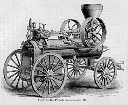
Fig. 116.-The Portable Steam Engine, 1878.
One of these engines, of 20 horse-power, has a steam cylinder 10 inchesin diameter and 18 inches stroke of piston, making 125 revolutions perminute, and has 9 square feet of grate-surface and 288 feet of heating-surface.It weighs about 4.5 tons. Steam is earried at 125 pounds. In the classof engines just described, the draught is obtained by the blast of theexhaust-steam which is led into the chimney. Such engines are now soldat from $120 to $150 per horse-power, according to size and quality, thesmaller engines costing most. The usual consumption of
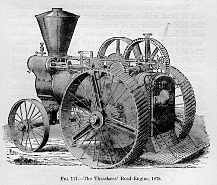
Fig. 117. The Thrashers' Road-Engine, 1878.
fuel is from 4 to 6 pounds per hour and per horse-power, burning from15 to 20 pounds on each square foot of grate, and each pound evaporatingabout 8 pounds of water. A usual weight is, for the larger sizes, 500 poundsper horsepower.
These engines are sometimes arranged to propel them selves, as in the Mills" Thrashers"' road-engine or locomotive, of which the accompanyingengraving is a good representation. This engine is proportioned for haulinga tank containing 10 barrels, or more, of water and a grainseparator overall ordinary roads, and to drive a thrashing-machine or saw-mill, developing20 or 25 horse-power. This example of the road-engine has a boiler builtto work at 250 pounds of steam; the engine is designed for a maximum powerof 30 horses.This engine has a balanced valve and automatic cut-off, andis fitted with a reversing-gear for use on the road. The driving-wheelsare of wrought-iron, 56 inches diameter and 8 inches wide, with cast-irondriving-arms. Both wheels are drivers on curves as well as on straightlines. The engine is guided and fired by one man, and the total weightis so small that it will pass safely over any good country bridge. A brakeis attached, to insure safety when going down-hill. Although designed tomove at a speed of about three miles per hour, the velocity of the pistonmay be increased so that four miles per hour may be accomplished when necessary.
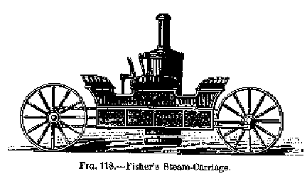
Fig. 118. Fisher's Steam-Carriage.
This is an excellent example of this kind of engine as constructed atthe present time. The strongly-built boiler, with its heater, the jacketedcylinder, and light, strong frame of the engine, the steel running-gear,the carefully covered surfaces of cylinder and boiler, and excellent proportionsof details, are illustrations of good modern engineering, and are in curiouscontrast with the first of the class, built a century earlier by Smeaton.Steam-carriages for passengers are now rarely built. Fig. 118 representsthat designed by Fisher about 1870 or earlier. It was only worked experimentally.
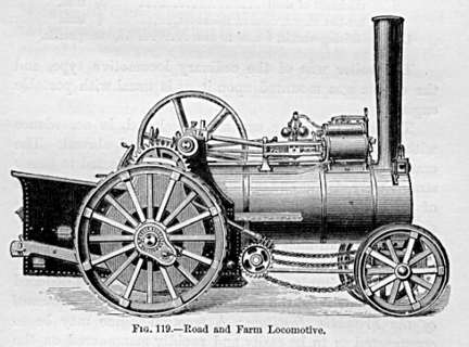
Fig. 119. Road and Farm Locomotive.
The above is an engraving of a road and farm locomotive as built byone of the most successful among several British firms engaged in thiswork.
The capacity of these engines has been determined by experiment by theauthor in the United States, and abroad by several distinguished engineers.
The author made a trial of one of these engines at South Orange, N. J.,to determine its power, speed, anal convenience of working and manceuvring.The following were the principal dimensions:
Weight of engine, complete, 5 tons 4 cwt. - 11,648 pounds.
Steam-cylinder diameter - 7.75 inches.
Stroke of piston - 10 inches.
Revolution of crank to one of driving-wheels - 17
Driving wheels diameter - 60 inches.
" breadth of tire - 10 inches.
" weight. each - 450 pounds.
Boiler length over all - 8 feet.
" diameter of shell - 30 feet.
" thickness of shell - .5 inch
" fire-box sheets, outside, thickness - .5 inch.
Load on driving-wheels, 4 tons 10 cwt - 10,080 pounds.
The boiler was of the ordinary locomotive type, and the engine was mountedupon it, as is usual with portable engines.
The steam-cylinder was steam-jacketed, in accordance with the most advancedpractice here and abroad. The crank-shaft and other wrought-iron partssubjected to heavy strains were strong and plainly finished. The gearingwas of malleableized cast-iron, and all bearings, from crankshaft to driving-wheel,on each side, were carried by a single sheet of half-inch plate, whichalso formed the sides of the firebox exterior.
The following is a summary of the conclusions deduced by the author fromthe trial, and published in the Journal of the Franklin Institute: A traction-enginemay be so constructed as to be easily and rapidly maneuvered on the commonroad; and an engine weighing over 5 tons may be turned continuously withoutdifficulty on a circle of 18 feet radius, or even on a road but littlewider than the length of the engine. A locomotive of 5 tons 4 hundred weighthas been constructed, capable of drawing on a good road 23,000 pounds upa grade of 533 feet to the mile, at the rate of four miles an hour; andone might be constructed to draw more than 63,000 pounds up a grade of225 feet to the mile, at the rate of two refiles an hour.
It was further shown that the coefficient of traction with heavily-ladenwagons on a good macadamized road is not far from .04; the traction-powerof this engine is equal to that of 20 horses; the weight, exclusive ofthe weight of the engine, that could be drawn on a level road, was 163,452pounds; and the amount of fuel required is estimated at 500 pounds a day.The advantages claimed for the traction-engine over horse-power are: nonecessity for a limitation of working-hours; a difference in first costin favor of steam; and in heavy work on a common road the expense by steamis less than 25 per cent. of the average cost of horse-power, a traction-enginecapable of doing the work of 25 horses being worked at as little expenseas 6 or 8 horses. The cost of hauling heavy loads has been estimated at7 cents per ton per mile.
Such engines are gradually becoming useful in steam-ploughing. Two systemsare adopted. In the one the engine is stationary, and hauls a " gang" of ploughs by means of a windlass and wire rope; in the other theengine traverses a field, drawing behind it a plough or a gang of ploughs.The latter method has been proposed for breaking up prairie-land.
Thus, thirty years after the defeat of the intelligent, courageous, andpersistent Hancock and his co-workers in the scheme of applying the steam-engineusefully on the common road, we find strong indications that, in a newform, the problem has been again attacked, and at least partially solved.
One of the most important of the prerequisites to ultimate success in thesubstitution of steam for animal power on the highway is that our roadsshall be well made. As the greatest care and judgment are exercised, andan immense outlay of capital is considered justifiable, in securing easyeasy grades and a smooth track on our railroad routes, we may readily believethat similar precaution and outlay will be found advisable in adulatingthe common road to the road-locomotive. It would seem to the engineer thatthe natural obstacles generally supposed to stand in the way have, afterall, no real existence. The principal inconvenience that may be anticipatedwill probably arise from the carelessness or avarice of proprietors, whichmay sometimes cause them to appoint ignorant and inefficient engine-drivers,giving them charge of what are always excellent servants, but terriblemasters. Nevertheless, as the transportation of passengers on railroadsis found to be attended with less liability to loss of life or injury ofperson than their carriage by stage-coach, it will be found, very probably,that the general use of steam in transporting freight on common roads maybe attended with less risk to life or property than to-day attends theuse of horse-power.
The STEAM FIRE-ENGINE is still another form of portable engine. It is alsoone of the latest of all applications of steam-power. The steam fire-engineis peculiarly an American production. Although previously attempted, theirpermanently successful introduction has only occurred within the last fifteenyears.
As early as 1830, Braithwaite and Ericsson, of London, England, built anengine with steam and pump cylinders of 7 and 6.5 inches diameter, respectively,with 16 inches stroke of piston This machine weighed 2.5 tons, and is saidto have thrown 150 gallons of water per minute to a height of between 80and 100 feet. It was ready for work in about 20 minutes after lightingthe fire. Braithwaite afterward supplied a more powerful engine to theKing of Prussia, in 1832. The first attempt made in the United States toconstruct a steam fire-engine was probably that of Hodge, who built onein New York in 1841. It was a strong and very effective machine, but wasfar too heavy for rapid transportation. The late J. K. Fisher, who throughouthis life persistently urged the use of steam-carriages and traction-engines,designing and building several, also planned a steam fire-engine. Two werebuilt from his design by the Novelty Works, New York, about 1860, for Messrs.Lee & Larned. They were "self-propellers," and one of them,built for the city of Philadelphia was sent to that city over the highway,driven by its own engines. The other was built for and used
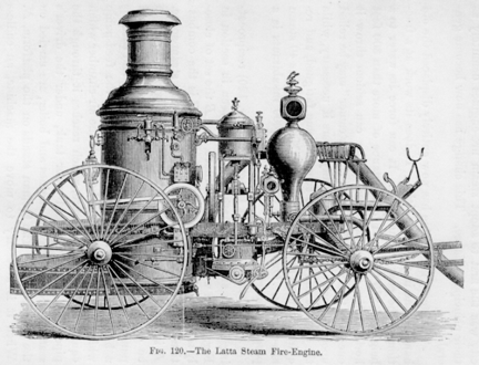
Fig. 120. - The Latta Steam Fire-Engine.
by the New York Fire Department, and did good service for several years.These engines were heavy, but very powerful, and were found to move atgood speed under steam and to maneuver well. The Messrs. Latta, of Cincinnati,soon after succeeder in constructing comparatively light and very effectiveengines, and the fire department of that city was the first to adopt steamfire-engines definitely as their principal reliance. This change has nowbecome general.
The steam fire-engine has now entirely displaced the old hand-engine inall large cities. It does its work at a fraction of the cost of the latter.It can force its water to a height of 22O feet, and to a distance of morethan 300 feet horizontally, while the hand-engine can seldom throw it one-thirdthese distances; and the " steamer " may be relied upon to workat full power many hours if necessary, while the men at the hand-enginesoon become fatigued, and require frequent relief. The city of New Yorkhas 40 steam fire-engines. One engine to every 10,000 inhabitants is aproper proportion.
In the standard steam fire-engine (Fig. 120) reciprocating engines andpumps are adopted, as seen in section in Fig. l2l, in which A is the furnace,and B the set of closely-set vertical fire-tubes in the boiler. C is thecombustion-chamber, D the smoke-pipe, and R the steamspace. E is the steam-cylinder,and F the pump, which is seen to be double-acting. There are two pairsof engines and pumps, working oil cranks, set at right angles, and turninga balance-wheel seen behind them. G is the feed-pump which supplies waterto the boiler, H the air-chamber which equalizes the water-pressure, whichreaches it through the pipe, IJ. K is the feed-water tank, under the driver'sseat, L, which, with the engines and boiler, are carried on the frame,MM: The fireman stands on the platform, N. When it is necessary to movethe machine, an endless chain connects the crank-shaft with the rearwheels,and the engine, with pumps shut off, is thus made to drive the wheels atany desired speed.
A self-propelling engine by the Amoskeag Company had the following dimensionsand performance: Weight, 4 tons; speed, 8 miles per hollr; steam-pressure,75 pounds per square inch; height of stream from l.25-inch nozzle, 225feet; l.75-inch nozzle, 150 feet; distance horizontally, 1.25
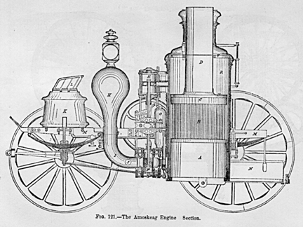
Fig. 121. - The Amoskeag Engine. Section.
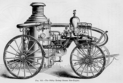
Fig. 122. - The Silsby Rotary Steam Fire-Engine.
inch nozzle, 300 feet; 1.75-inch, 250 feet a performance which contrastswonderfully with that of the hand-worked fire-engine which these engineshave now superseded.
It has recently become common to construct the steam fire-engine with rotaryengine and pump (Fig. 122). The superiority of a rotary motion for a steam-engineis apparently so evident that many attempts have been made to overcomethe practical difficulties to which it is subject. One of these difficulties,and the principal one, has been the packing of the part which performsthe office of the piston in the straight cylinder. Robert Stephenson onceexpressed the opinion that a rotary engine would never be made to worksuccessfully, on account of this difficulty of packing. The most palpableof the advantages of the rotary engine are the reduction in the size ofthe engine, claimed to result from the gleat velocity of the piston; theavoidance of great accidental strains, especially noticed in propellingships; and a great saving of the power which is asserted to be expendedin the reciprocating engine in overcoming the inertia while changing thedirection of the motions. These advantages adapt the rotary engine, inan especial manner, to the driving of a locomotive or steam fire-engine.
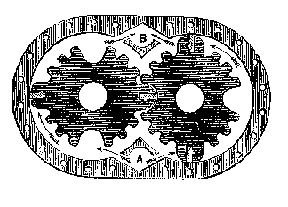
Fig. 123. - Rotary Steam-Engine.
In the Holly rotary engine, seen in Fig. 123, eccentrics and sliding-cams,which are frequently used in rotary engines, and which are objectionableon account of their great friction, are avoided. Corrugated pistons, orirregular cams, C D, are adopted, forming chambers within the cases. Inthe engine the steam enters at A, at the bottom of the case, and pressesthe cams apart. The only packing used is in the ends of the long metalcogs, which are ground to fit the case and are kept out by the momentumof the cams, assisted by a slight spring back of the packing-pieces. Thefriction on the pump (Fig. 124) is said to be less than in
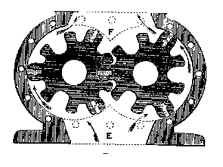
Fig. 124. Rotary Pump.
the engine. This is the reason given in support of the claim that therotary engine forees water to a given distance with from one-fourth toone-third the steam-pressure necessary to drive all reciprocating engines.The smaller amount of power necessary to do the work, the less strain andconsequent wear and tear upon the whole machine, are said to make it moredurable and reliable. The pump being chambered, its liability to injuryby the use of dirty or gritty water is lessened, and it is stated thatit will last for years, pumping gritty water that would soon cut out apiston-pump. The pump used with this engine is, as shown in the above illustration,somewhat similar to the rotary engine driving it. Each of the revolvingpistons has three long teeth bearing against the cylinder, and packed,to prevent leakage, like the engine-cams. They are carried on steel shaftscoupled to the engine-shafts. The water enters at E and is discharge atF, and the passages are purposely made large in order that sand, chips,and dirt, which may enter with the water, may pass through.
The rotary engine is gradually coming into use for various special purposes,where small power is called for, and where economy of fuel is not important;but it has never yet competed, and may perhaps never in the future compete,with the reciprocating-piston engine where large engines are required,or where even moderate economy of fuel is essential. This form of enginehas assumed so little importance, in fact, in the application of the steam-engine,that comparatively little is known of its history. Watt invented a rotaryengine, and Yule many years afterward (1836) constructed such engines atGlasgow. Lamb patented another in 1842, Behrens still another in l847.Napier, Hall, Massey, Holly, La France, and others, have built enginesof this class in later times. Nearly all consist either of canls rotatingin gear, as in those above sketched, or of a piston set radially in a cylinderof small diameter, which turns on its axis within a much larger cylinderset eccentrically, the piston, as the former turns, sliding in and outof the smaller cylinder as its outer edge slides in contact with the innersurface of the larger. In some forms of rotary engine, a piston revolveson a central shaft, and a sliding abutment in the external cylinder servesto separate the steam from the exhaust side and to confine the steam expandingwhile doing work. Nearly all of these combinations are also used as pumps.
Fire-engines, made by the best-known American builders of engines, withreciprocating engines and pumps, such as are in general use in the UnitedStates, have become standard in general plan and arrangement of details.These are probably the best illustrations of extreme lightness, combinedwith strength of parts and working power, which have ever been producedin any branch of mechanical engineering. Icy using a small boiler crowdedwith heating-surface, very carefully proportioned and arranged, and withsmall water-spaces; by adopting steel for running-gear and working partswherever possible; by working at high piston-speed and with high steam-pressure;by selecting fuel with extreme care by all these expedients, the steamfire-engine has been brought, in this country, to a state of efficiencyfar superior to anything seen elsewhere. Steam is raised with wonderfulpromptness, even from cold water, and water is thrown from the nozzle atthe end of long lines of hose to great distances. But this combinationof lightness vith power is only attained at the expense of a certain regularityof action which can only be secured by greater water and steam capacityin the boiler. The small quantity of water contained within the boilermakes it neeessary to give constant attention to the feed, and the tendeney,almost invariably observed, to serious foaming and priming not only compelsintermitted eare while running, but even introduces an element of dangerwhich is not to be despised, even though the machine be in charge of themost experienced and skillful attendants. Even the greatest care, directedby the utmtost skill, would not avail to prevent frequent explosions, wereit not for the fact that it rarely, if ever, happens that accidents tosuch boilers occur from low water, unless the boiler is actually completelyemptied of water. In driving them at fires, they frequently foam so violentlythat it is utterly impossible to obtain any clew to the amount of waterpresent and the attendant usually keeps his feed-pump on and allows thefoaming to go on. As long as water is passing into the boiler it is veryunlikely that any portion will become overheated and that accident willoccur. Such management appearss very reckless, and yet accident from sucha cause is exceedingly rare.
The changes which have been made in LOCOMOTIVE-CONSTRUCTION during thepast few years have also been in the direction of the refinement of theearlier designs, and have been accompanied by corresponding changes inall branches of railroad-work. The adjustment of parts to each other andproportioning them to their work, the modification of the minor detailsto suit changes of general dimensions, the improvement of workmanship,and the use of better material, have signalized this latest period. Specialforms of engine have been devised for special kinds of work. Small, lighttank-engines (Fig. 125), carrying
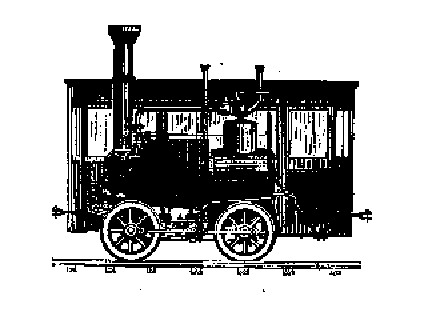
Fig. 125.-Tank-Engine, New York Elevated Railroad.
their own fuel and water without "tenders," are used for movingcars about terminal stations and for making up trains; powerful, heavy,slow-moving engines, of large boiler-capacity and with small wheels, areused on steep gradients and for hauling long trains laden with coal andheavy merchandise; and hardly less powerful but quite differently proportioned"express"-engincs are used for pssenger and mail service.
A peculiar form of engine (Fig. 126) has been designed by Forney, in whichthe whole weight of engine, tender, coal, anal water, is carried by oneframe and on one set of wheels, the permanent weight falling on the driving-wheelsand the variable load on the truck. These engines have also a comparativelyshort wheel-base and high pulling-power. The lightest tank-engines of thefirst class mentioned weigh 8 or l0 tons; but engines much lighter thanthese, even, are built for mines, where they are sent into the gallerirsto bring out the coal-laden wagons. The heaviest engines of this classattain weights of 20 or 30 tons. The
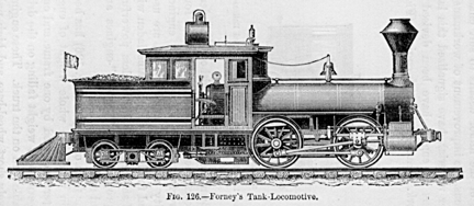
Fig. 126.-Forney's Tank-Locomotive.
heaviest engine yet constructed in the United States is said to be onein use on the Philadelphia & Reading Railroad, having a weight of about100,000 pounds, which is carried on 12 driving-wheels.
A locomotive has two steam-cylinders, either side by side within the frame,and immediately beneath the forward end of the boiler, or on each sideand exterior to the frame. The engines are non-condensing, and of the simplestpossible construction. The whole machine is carried upon strong but flexiblesteel springs. The steam-pressure is usually more than 100 pounds. Thepulling-power is generally about one-fifth the weight under most favorableconditions, and becomes as low as one-tenth on wet rails. The fuel employedis wood in new countries, coke in bituminous coal districts, and anthracitecoal in the eastern part of the United States. The general arrangementand the proportions of locomotives differ somewhat in different localities.In Fig. 127, a British
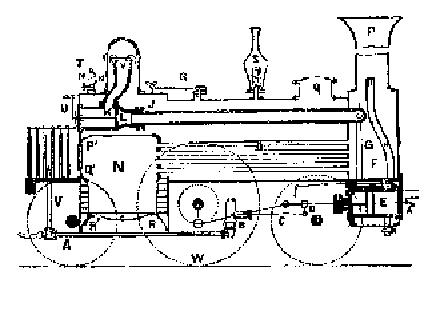
Fig. 127. British Express Engine.
express-engine, O, is the boiler, N the fire-box, X the grate, G thesmoke-box, and P the chimney. S is a spring and R a lever safety-valve,T is the whistle, L, the throttle or regulator valve, E the steam-cylinder,and W the driving-wheel. The force-pump, B C, is driven from the crosshead,D. The frame is the base of the whole system, and all other parts are firmlysecured to it. The boiler is made fast at one end, and provision is madefor its expansion when heated. Adhesion is secured by throwing a properproportion of the weight upon the driving-wheel, Bv: This is from about6,000 pounds on standard freight-engines,
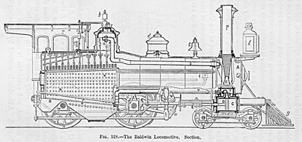
Fig. 128.-The Baldwin Locomotive. Section.
having several pairs of drivers, to 10,000 pounds on passenger-engines,per axle. The peculiarities of the American type (Fig. 128) are the truck,IJ, or bogie, supporting the forward part of the engine, the system ofequalizers, or beams which distribute the weight of the machine equallyover the several axles, and minor differences of detail. The cab or house,r, protecting the engine-driver and fireman, is an American device, whichis gradually coming into use abroad also. The American locomotive is distinguishedby its flexibility and ease of action upon even roughly-laid roads. Inthe sketch, which shows a standard American engine in section, A B is theboiler, C one of the steam-cylinders, D the piston, E the cross-head, connectedto the crank-shaft, F, by the connecting-rod, G H the drivingwheels, IJ the truck-wheels, carrying the truck, K L; M N is the fire-box, O O thetubes, of which but four are shown. The steam-pipe, R S, leads the steamto the valve-chest, T, in which is seen the valve, moved by the valve-gear,U V, and the link, W. The link is raised or depressed by a lever, X movedfrom the cab. The safety-valve is seen at the top of the dome, at Y, andthe spring-balance by which the load is adjusted is shown at Z. At a isthe cone-shaped exhaust-pipe, by which a good draught is secured. The attachmentsb, c, d, e, f, g whistle, steam-gauge, sand-box, bell, head-light,and "cow-catcher" are neatly all peculiar, either in constructionor location, to the American locomotive. The cost of passenger-locomotivesof ordinary size is about $12,000; heavier engines sometimes cost $20,000.The locomotive is usually furnished with a tender, which carries its fueland water. The standard passenger-engine on the Pennsylvania Railroad hasfour driving-wheels, 5.5 feet diameter; steam-cylinders, 17 inches diameterand 2 feet stroke; grate-surface 15.5 square feet, and heating-surface1,058 square feet. It weighs 63,100 pounds, of which 39,000 pounds areon the drivers and 24,100 on the truck. The freight-engine has six drivingwheels, 54.5 inches in diameter. The steam-cylinders are 18 inches in diameter,stroke 22 inches, grate-surface 14.8 square feet, heating-surface 1,096feet. It weighs 68,500
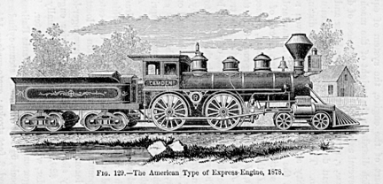
Fig. 129.-The American Type of Express-Engine, 1878.
pounds, of which 48,000 are on the drivers and 20,500 on the truck.The former takes a train of five cars up an average grade of 90 feet tothe mile. The latter is attached to a train of 11 cars. On a grade of 50feet to the mile, the former takes 7 and the latter 17 cars. Tank-enginesfor very heavy work, such as on grades of 320 feet to the mile, which arcfound on some of the mountain lines of road, are made with five pairs ofdriving-wheels, and with no truck. The steam-cylinders are 20.125 inchesin diameter, 2 feet stroke; grate-area, 15.75 feet; heating-surface, 1,380feet; weight with tank full, and full supply of wood, 112,000 pounds; averageweight, 108,000 pounds. Such an engine has hauled 110 tons up this gradeat the speed of 5 miles an hour, the steam-pressure being 145 pounds. Theadhesion was about 23 per cent. of the weight.
In checking a train in motion, the inertia of the engine itself absorbsa seriously large portion of the work of the brakes. This is sometimesreduced by reversing the engine and allowing the steam-prcssure to actin aid of the brakes. To avoid injury by abrasion of the surfaces of piston,cylinder, and the valves and valve-seats, M. Le Chatelier introduces ajet of steam into the exhaust-passages when reversing, and thus preventsthe ingress of dust-laden air and the drying of the rubbing surfaces. Thismethod of checking a train is rarely resorted to, however, except in caseof danger. The introduction of the "continuous" or " air" brake, which can be thrown into action in an instant on every carof the train by the engine-driver, is so efficient that it is now almostuniversally adopted. It is one of the most important safeguards which Americaningenuity has yet devised. In drawing a train weighing 150 tons at therate of 60 miles an hour, about 800 effective horse-power is required.A speed of 80 miles an hour has been often attained, and 100 miles hasprobably been reached.
The American locomotive-engine has a maximum life which may be stated atabout 30 years. The annual cost of repairs is from 10 to 15 per cent. ofits first cost. On moderately level roads, the engine requires a pint ofoil to each 25 miles, and a ton of coal to each 40 or 50 miles run.
Although the above sketch and description represent the cobstruction andperformance of the standard loeomotive of the present time, there are indicationsthat the compound arrangement of engines will ultimately be adopted. Thiswill involve a considerable change of proportions greatly increasing thevolume and weight of steam-cylinders, but enabling the designer to morethan proportionally decrease the weight of boiler and the quantity of fuelcarried. There is no serious objection to their use, however, and no insuperabledifficulty in the construction of the "double-cylinder" typeof engine for the locomotive. A few such engines have already been putin service. In these engines the high-pressure cylinder is placed on oneside and the larger low-pressure cylinder on the other side of the locomotive,thus having but two cylinders, as in the older plan. The valve-gear isthe Stephenson link, as in the ordinary engine. At starting, the steamis allowed to act on both pistons; but after a few revolutions the courseof the steam is changed, and the exhaust from the smaller cylinder, insteadof passing into the chimney, is sent to the larger cylinder, which is atthe same time cut off from the main steam-pipe. When the engine is ascendinga steep gradient the steam may, if necessary, be taken from the boilerinto both cylinders, as when starting.
Compound engines of this kind have been used on the French line of railroadfrom Bayonne to Biarritz. They were designed by Mallet and built at LeCreuzot. The steam-cylinders are of 9.5 and 15.75 inches diameter, andof 17.75 inches stroke of piston. The four driving-wheels are 4 feet indiameters and the total weight of engine is 20 tons. The boiler has 484.5square feet of heating-surface, and is built to carry 10 atmospheres pressure.When hauling trains of 50 tons at 25 miles an hour, these engines requireabout 15 pounds of good coal per mile.
The total length of the railways in operation in the United States on the1st day of January, 1877, was 76,640 miles,l being an average of one mileof railroad for every 600 inhabitants.
In 1873 came the great financial crisis, with its terrible results of interruptedproduction, poverty, and starvation, and an almost total cessation of thework of building new railroads. The largest number of miles ever builtin any one year were constructed in 1872. The greatest mileage is in Illinois,reaching 6,589; the smallest in Rhode Island, 136, and in Washington Territory,110. The State of Massachusetts has one mile of railroad to 4.86
1 January,1878, about 80,000 miles.
miles of territory, this ratio being the greatest in the country. Thelongest road in operation is the Chicago N; Northwestern, extending 1,500miles; the shortest, the Little Saw-Mill Run Road in Pennsylvania, whichis but three miles in length. The total capital of railways in the countryis $6,000,000,000, or an average of $100,000 per mile. The earnings forthe year 1872 amounted to $454,969,000, or $7,500 per mile. The largestnet earnings recorded as made on any road were gained by the New York Central& Hudson River, $8,260,827; the smallest on several roads which notonly earned nothing, hut incurred a loss.
The catastrophe of 1873-'74 revealed the fact that the latter conditionof railroad finances was vastly more common than had been suspected; andit is still doubtful whether the existing immense network of railroadswhich covers the United States ean be made, as a whole, to pay even a moderatereturn on the money invested in their construction.
The railroads in Great Britain comprise over 15,000 miles of track nowbeing worked in the United Kingdom, on which have been expended $2,800,000,000.This sum is equal to five times the amount of the annual value of all thereal property in Great Britain, and two-thirds of the national debt. Afterdeducting all the working expenses, the gross net annual revenue of allthe roads exceeds by $110,000,000 the total revenue from all sources ofBelgium, Holland, Portugal, Denmark, Sweden and Norway. An army of 100,000officers and servants is in the employ of the companies, and the valueof the rolling-stock exceeds $150,000,000.
SECTION III. MARINE ENGINES.
The changes which have now beeome completed in the marine steam-enginehave been effected at a later date than those which produced the modernlocomotive. On the American rivers the modification of the beam-enginesince the time of Robert L. Stevens has been very slight. The same generalarrangement is retained, and the details are little, if at all, altered.The pressure of steam is sometimes as high as 60 pounds per square inch.The valves are of the disk or poppet variety, rising and falling vertically.They are four in number, two steam and two exhaust valves being placedat each end of the steam-cylinder. The beam-engine is a peculiarly Americantype, seldom if ever seen abroad. Fig. 130 is an outline sketch of thisengine as built for a steamer plying on the Hudson River. This class ofengine is usually adopted in vessels of great length, light draughts andhigh speed. But one steam-cylinder is commonly used. The cross-head iscoupled to one end of the beam by means of a pair of links, and the motionof the opposite end of the beam is transmitted to the crank by a connecting-rodof moderate length. The beam has a cast-iron centre surrounded by a wrought-ironstrap of lozenge shape, in which are forged the bosses for the end-centres,or for the pins to which the connecting-rod and the links are attached.The main centre of the beam is supported by a "gallows-frame "of timbers so arranged as to receive all stresses longitudinally.
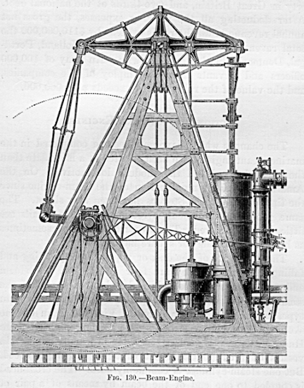
Fig. 130.-Beam-Engine.
The crank and shaft are of wrought-iron. The valve-gear is usually ofthe form already mentioned as the Stevens valve-gear, the invention ofRobert L. and Francis B. Stevens. The condenser is placed immediately beneaththe steam-cylinder. The air-pump is placed close beside it, and workedby a rod attached to the beam. Steam-vessels on the Hudson River have beendriven by such engines at the rate of 20 miles an hour. This form of engineis remarkable for its smootlmess of operation, its economy and durability,its compactness, and the latitude which it permits in the change of shapeof the long, flexible vessels in which it is generally used, without injuryby "getting out of line." For paddle-engines of large vessels,the favorite type,
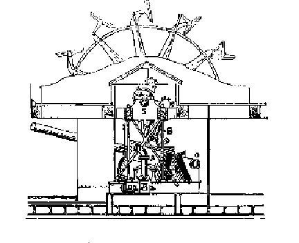
Fig. 13l. Oscillating Engine and Feathering Paddle-Wheel.
which has been the side-lever engine, is now rarely built. For smallervessels, the oscillating engine with feathering paddle-wheels is stilllargely employed in Europe. This style of engine is shown in Fig. 131.It is very compact, light, and moderately economical, and excels in simplicity.The usual arrangement is such that the feathering-wheel has the same actionupon the water as a radial wheel of double diameter. This reduction ofthe diameter of the wheel, while retaining maximum effectiveness, permitsa high speed of engine, and therefore less weight, volume, and cost. Thesmaller wheel-boxes, by offering less resistance to the wind, retard theprogress of the vessel less than those of radial wheels. Inclined enginesare sometimes used for driving paddle-wheels. In these the steam-cylinderlies in an inclined position, and its connecting-rod directly connectsthe crank with the cross-head. The condenser and air-pump usually lie beneaththe cross-head guides, and are worked by a bell-crank driven by links oneach side the connecting-rod, attached to the cross-head. Such enginesare used to some extent in Europe, and they have been adopted in the UnitedStates navy for side-wheel gunboats. They are also used on the ferry-boatsplying between New York and Brooklyn.
Among the finest illustrations of recent practice in the construction ofside-wheel steamers are those built for the several routes between NewYork and the cities of New England which traverse Long Island Sound. Ourillustration exhibits the form of these vessels, and also shows well themodifications in structure and size which have been made during this generation.The later vessel is 325 feet long, 45 feet beam, 80 feet wide over the"guards," and 16 feet deep, drawing 10 feet of water. The "frames"upon which the planking of the hull is fastened are of white-oak, and thelighter and "top " timbers of cedar and locust. The engine hasa steam-cylinder 90 inches in diameter and 12 feet stroke of piston.1 Oneach side the great saloons which extend from end to end of the upper deekare state-rooms, containing each two berths and elegantly furnished. Theengine of this vessel is capable of developing about 2,500 horse-power.The great wheels, of which the paddleboxes are seen rising nearly to theheight of the hurricane-deck, are 37.5 feet in diameter and 12 in breadth.The hull of this vessel, including all wood-work, weighs over 1,200 tons.The weight of the machinery is about 625 tons. The steamer makes 16 knotsan hour when the engine is at its best speed about 17 revolutions perminute and its
l The engines of steamers Bristol and Providence are 110inches in diameter, and of 12 feet stroke.
average speed is about 14 knots on its route of 160 miles. The coal requiredto supply the furnaces of such a vessel and with such machinery would beabout 3 tons per hour,
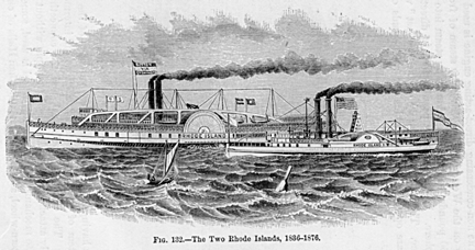
Fig. 132.-The Two Rhode Islands, 1836-1876.
or a little over 2.5 pounds per horse-power. The construction of sucha vessel occupies, usually, about a year, and costs a quarter of a milliondollars.
The non-condensing direct-acting engine is used principally on the Westernrivers, driven by steam of from 100 to 150 pounds pressure, and exhaustsits steam into the atmosphere. It is the simplest possible form of direct-actingengine. The valves are usually of the " poppet " variety, andare operated by cams which act at the ends of long
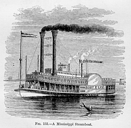
Fig. 133. A Mississippi Steamboat.
levers having their fulcra on the opposite side of the valve, the stemof which latter is attached at an intermediate point. The engine is horizontal,and the connecting-rod directly attached to cross-head and crank-pin withoutintermediate mechanism. The paddle-wheel is used, sometimes as a stern-wheel,as in the plan of Jonathan Hulls of one and a half century ago, sometimesas a side-wheel, as is most usual elsewhere. One of the most noted of thesesteamers, plying on the Mississippi, is shown in the preceding sketch.
The largest steamer on the Mississippi is the Grand Republic, a vessel340 feet long, 56 feet beam, and 10.25 feet depth. The draught of waterof this great craft is but 3.5 at feet forward and 4.5 aft. The two setsof compound engines, 28 and 56 inches diameter and of 10 feet stroke, drivewheels 38.5 feet in diameter and 18 feet wide. The boilers are of steel.A steamer built still later on the Ohio has the following dimensions: Lengths225 feet; breadth 35.5 feet; depth, 5 feet; cylinders, 17.25 inches indiameter, 6 feet stroke; three boilers. The hull and cabin were built atJeffcrsonville, Ind. She has 40 large state-rooms. The cost of the steamerwas $ 40,000.
These vessels have now opened to commerce the whole extent of the greatMississippi basin, transporting a large shale of the products of a sectionof country measuring a million and a half square miles an area equalto many times that of New York State, and twelve times that of the islandof Great Britain an area exceeding that of the whole of Europe, exclusiveof Russia and Turkey, and capable, if as thoroughly cultivated as the Netherlands,of supporting a population of between three and four hundred millions ofpeople.
The steam-engine and propelling apparatus of the modern ocean-steamer havenow become almost exclusively the compound or double-cylinder engine, drivingthe screw. The form and the location of the machinery in the vessel varywith the size and character of the ship which it drives. Very small boatsare fitted with machinery of quite a different kind from that built forlarge steamers, and war-vessels have usually been supplied with enginesof a design radically different from that adopted for merchant-steamers.
The introduction of Steam-Launches and small pleasure-boats driven by steam-poweris of comparatively recent date, but their use is rapidly increasing. Thosefirst built were heavy, slow, and complicated; but, profiting by experience,
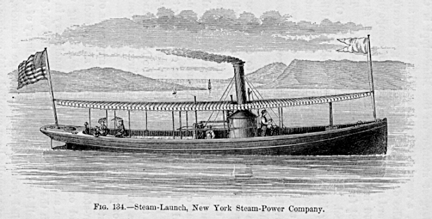
Fig. 134.-Steam-Launch, New York Steam-Power Company.
light and graceful boats are now built, of remarkable swiftness, andhaving such improved and simplified machinery that they require littlefuel and can be easily managed. Such boats have strong, carefully-modeledhulls, light and strong boilers, capable of making a large amount of drysteam with little fuel, and a light, quick-running
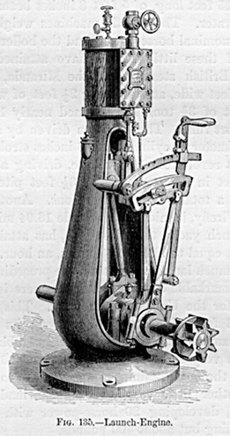
Fig. 135 Launch-Engine.
engine, working without shake or jar, and using steam economically.
The above sketch represents the engine built by a New York firm for suchlittle craft. This is the smallest size made for the market. It has a steam-cylinder3 inches in diameter and a stroke of piston of 5 inches, driving a screw26 inches in diameter and of 3 feet pitch. The maximum power of the engineis four or five times the nominal power. The boiler is of the form shownin the illustrations of semi-portable engines, and has a heating-surface,in this case, of 75 square feet. The boat itself is like that seen on page386, and is 25 feet long, of 5 feet 8 inches beam, and draws 25 feet ofwater. These little machines weigh about 150 pounds per nominal horse-power,and the boilers about 300.
Some of these little vessels have attained wonderful speed. A British steam-yacht,the Miranda, 45.5 feet in length, 5.75 feet wide, and drawing 2.5 feetof water, with a total weight of 3.75 tons, has steamed nearly 18.5 milesan hour for short runs. The boat was driven by an engine of 6 inches diameterof cylinder and 8 inches stroke of piston, making 600 revolutions per minute,driving a two-bladed screw 2.5 feet in diameter and of 3.33 feet pitch.Its machinery had a total weight of two tons. Another English yacht, theFirefly, is said to have made 18.94 miles an hour. A little French yacht,the Hirondelle, has attained a speed of 16 knots, equal to about 18.94miles, an hour. This was, however, a much larger vessel than the preceding.One of the most remarkable of these little steamers is a torpedo-boat builtfor the United States navy. This vessel is 60 feet long, 6 feet wide, and5 feet deep; its screw is 38 inches in diameter and of 5 feet pitch, two-bladed,and is driven, by a very light engine and boiler, 400 revolutions per minute,the boat attaining a speed of 19 to 20 miles an hour. Another little vessel,the Vision, made nearly as great speed, developing 20 horse-power withengine and boiler weighing but about 400 pounds.
Yachts of high speed require such weight and bulk of engine that but littlespace is left for cabins, and they are usually exceedingly uncomfortablevessels. In the Miranda the weight of machinery is more than one-half thetotal weight of the whole. An illustration of the more comfortable andmore generally liked pleasure-yacht is the Day Dream. The length is 105feet, and the boat draws 5.5 feet of water. There are two engines, havingsteamcylinders 14 inches in diameter and of the same length of stroke,direct-acting, condensing, and driving a screw, of 7 feet diameter andof 10.5 feet pitch, 135 revolutions a minute, giving the yacht a speedof 131 knots an hour.
In larger vessels, as in yachts, in nearly all eases, the ordinary screw-engineis dilect-acting. Two engines are placed side by side, with cranks on theshaft at an angle of 90° with each other. In merchant-steamers thesteam-cylinders are usually vertical and directly over the crank-pins,to whieh the cross-heads are coupled. The condenser is placed behind theengine-frame, or, where a jet-condenser is used, the frame itself is sometimesmade hollow, and serves as a condenser. The air-pump is worked by a beamconnected by links with the cross-head. The general arrangement is likethat shown in Figs. 137 and 138. For naval purposes such a form is objectionable,since its height is so great that it would be exposed to injury by
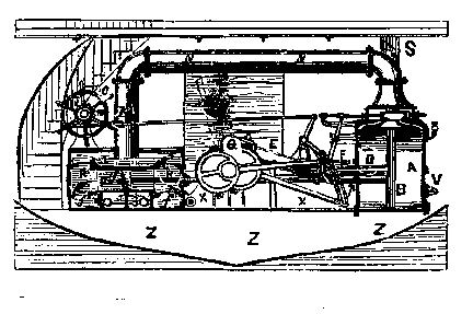
Fig. 136. Horizontal, Direct-acting Naval Screw-Engine.
shot. In naval engineering the cylinder is placed horizontally, as inFig. 136, which is a sectional view, representing an horizontal, direct-actingnaval screw-engine, with jet-condenser and double-acting air and circulatingpumps. A is the steam-cylinder, B the piston, which is connected to thecrank-pin by the piston-rod, D, and connecting-rod, E. F is the cross-headguide. The eccentrics, G, operate the valve, which is of the "three-portedvariety," by a Stephenson link. Reversing is effected by the hand-wheel,C, which, by means of a gear, m, and a rack, k, elevates and depressesthe link, and thus reverses the valve. The trunk-engine, in which the connecting-rodis attached
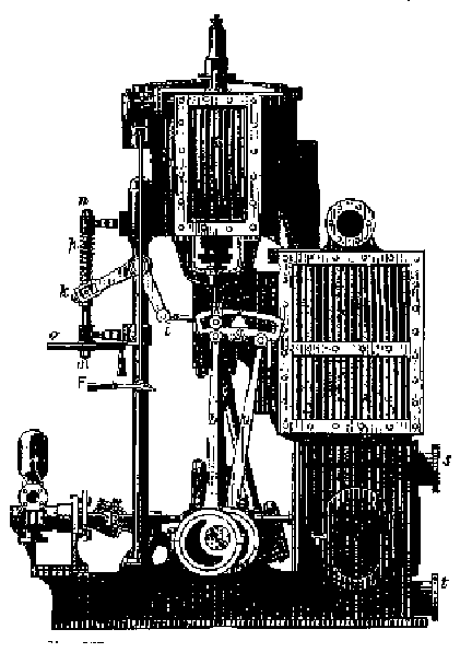
Fig. 137.-Compound Marine Engine. Side Elevation.
directly to the piston and vibrates within a trunk or cylinder securedto the piston, moving with it, and extending outside the cylinder, likean immense hollow piston-rod, is frequently used in the British navy. Ithas rarely been adopted in the United States.
In nearly all steam-vessels which have been built for the merchant servicerecently, and in some naval vessels, the compound engine has been adopted.Figs. 137 and 138 represent the usual form of this engine. Here A A, BB are the small and the large, or the high-pressure and the low-pressurecylinders respectively. C C are the valve
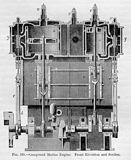
Fig. 138-Compound Marine Engine. Front Elevation and Section.
chests. G G is the condenser, which is invariably a surface-condenser.The condensing water is sometimes directed around the tubes contained withinthe casing, G G. while the steam is exhausted around them and among them,and sometimes the steam is condensed within the tubes, while the injection-waterwater which is sent into the condenser to produce condensation passes aroundthe exterior of the tubes. In either case, the tubes are usually of smalldiameter, varying from five-eighths to half an inch, and in length fromfour to seven feet. The extent of heating-surface is usually from one-halfto three-fourths that of the heating-surface of the boilers.
The air and circulating pumps are placed on the lower part of the condenser-casting,and are operated by a crank on the main shaft at N; or they are sometimesplaced as in the style of engine last described, and driven by a beam workedby the cross-head. The piston-rods, TS, are guided by the cross-heads,V V, working in slipper-guides, and to these cross-heads are attached theconnecting-rods, X X, driving the cranks, MM. The cranks are now usuallyset at right angles; in some engines this angle is increased to 120°,or even 180°. Where it is arranged as here shown, an intermediate reservoir,P O, is placed between the two cylinders to prevent the excessive variationsof pressure that would otherwise accompany the varying relative motionsof the pistons, as the steam passes from the high-pressure to the low-pressurecylinder. Steam from the boilers enters the high-pressure steam-chest,X, and is admitted by the steam-valve alternately above and below the pistonas usual. The exhaust steam is conducted through the exhaust passage aroundinto the reservoir, P, whence it it is taken by the low-pressure cylinder,precisely as the smaller cylinder drew its steam from the boiler. Fromthe large or low-pressure cylinder the steam is exhausted into the condenser.The valve-gear is usually a Stephenson link, g e, the position of whichis determined, and the reversal of which is accomplislled, by a hand-wheel,o, and screw, m n p, which, by the bell-crank, k i, are attached to thelink, g e. The " box-framing " forms also the hot-well. The surface-condenseris cleared by a single-acting air pump, inside the frame, at T. The feed-pumpand the bilge-pumps are driven from the cross-head of the air-pump.
The successful introduction of the double-cylinder engine was finally accomplishedby the exertions of a few engineers, who were at once intelligent enoughto understand its advantages, and energetic and enterprising enough topush it forward in spite of active opposition, and powerful enough, pecuniarilyand in influence, to succeed.

John Elder
The most active and earnest of these eminent men was John Elder, ofthe firm of Randolph, Elder & Co., subsequently John Eldler & Co.,of Glasgow.l
Elder was of Scotch descent. His ancestors had, for
1 Vide "Memoir of John Elder," W. J. M. Rankine,Glasgow, 1871.
generations, shown great skill and talent in construction, and had alwaysbeen known as successful millwrights. John Elder was born at Glasgow, March8, 1824, and died in London, September 17, 1869. He was educated at theGlasgow High-School and in the College of Engineering at the Universityof Glasgow, where, however, his attendance was but for a short time. Helearned the trade under his father in the workshops of the Messrs. Napier,and became an unusually expert draughtsman. After spending three yearsin charge of the drawing-office at the engine-building works of RobertNapier, where his father had been manager, Elder became a partner in firmwhich had previously been known as Randolph, Elliott & Co., in theyear 1852. The firm commenced building iron vessels in 1860.
In the mean time, the experiments of Hornblower and Wolff, of Allaire andSmith, and of McNaught, Craddock, and Nicholson, together with the theoreticalinvestigations of Thompson, Rankine, Clausius, and others, had shown plainlyin what direction to look for improvement upon then standard engines, andwhat direction practice was taking with all types. The practical deductionswhich were becoming evident were recognized very early by Elder, and hepromptly began to put in praetice the principles which his knowledge ofthermo-dynamics and of mechanics enabled him to appreciate. He adoptedthe compound engine, and coupled his cranks at angles of 180°, in orderto avoid losses due to the friction of the crank-shaft in its bearings,by effecting a partial counterbalancing of pressures on the journals. Elderwas one of the first to point out the fact that the compound engine hadproved itself more efficient than the single-cylinder engine, only whenthe pressure of steam carried and the extent to which expansion was adoptedexceeded the customary practice of his time. His own practice was, fromthe first, successful, and from 1853 to 1867 he and his partners wele continuallyengaged in the construction of steamers and fitting them with compoundengines.
The engines of their first vessel, the Brandon, required but 3.25-poundsof coal per hour and per horsepower, in 1854, when the usual consumptionwas a third more. Five years later, they had built engines which consumeda third less than those of the Brandon; and thenceforward, for many years,their engines, when of large size, exhibited what was then thought remarkableeconomy, running on a consumption of from 2.25 to 2.5 pounds.
In the year 1865 the British Government ordered a competitive trial ofthree naval vessels, which only differed in the form of their engines.The Arethusa was fitted with trunk-engines of the ordinary kind; the Octaviahad three steam-cylinders, coupled to three cranks placed at angles of120° with eaeh other; and the Constance was fitted with compound engines,two sets of three cylinders each, and each taking steam from the boilerinto one cylinder, passing it through the other two with continuous expansion,and finally exhausting from the third into the condenser. These vessels,during one week's steaming at sea, averaged, respectively, 3.64, 3.17,and 2.51 pounds of coal per hour and per horse-power, and the Constaneeshowed a marked superiority in the efficieney of the mechanism of her engines,when the losses by friction were compared.
The change from the side-lever single-cylinder engine, with jet-condenserand paddle-wheels, to the direct-acting compound engine, with surface-condenserand screwpropellers, has occurred Within the memory and under the observationof even young engineers, and it may be considered that the revolution hasnot been completely effected. This change in the design of engine is notas great as it at first seemed likely to become. Builders have but slowlylearned the principles stated above in reference to expansion in one ormore cylinders, and the earlier engines were made with a high and low pressurecylinder working on the same connecting-rod, and each machine consistedof four steam-cylinders. It was at last discovered that a high-pressuresingle-cylinder engine exhausting into a separate larger low-pressureengine might give good results, and the compound engine became as simpleas the type of engine which it displaced. This independence of high andlow pressure engines is not in itself novel, for the plan of using theexhaust of a high-pressure engine to drive a low-pressure condensing enginewas one of the earliest of known combinations.
The advantage of introducing double engines at sea is considerably greaterthan on land. The coal earried by a steam-vessel is not only an item ofgreat importance in consequence of its first cost, but, displacing itsweight or bulk of freight which might otherwise be carried, it representsso much non-paying cargo, and is to be charged with the full cost of transportationin addition to first cost. The best of steam-coal is therefore usuallychosen for steamers making long voyages, and the necessity of obtainingthe most economical engines is at ones seen, and is fully appreciated bysteamship proprietors. Again, an economy of one-fourth of a pound per horse-powerper hour gives, on a large transatlantic steamer, a saving of about 100tons of coal for a single voyage. To this saving of cost is to bc addedthe grill in wages and sustenance of the labor required to halldle thatcoal, and the gain by 100 tons of freight carried in place of the coal.
For many years the change which has here been outlined, in the forms ofengine and the working of steam expansively, was retarded by the inefficiencyof methods and tools used in construction. With gradual improvement intools and in methods of doing work, it became possible to control highersteam and to work it successfully; and the change in this direction hasbeen steadily going on up to the present time with all types of steam-engine.At sea this rise of pressure was for a considerable time retarded by theserious difficulty encountered in the tendency of the sulphate of limeto deposit in the boiler. When steam-pressure had risen to 25 pounds persquare inch, it was found that no amount of "blowing out" wouldprevent the deposition of seriously large quantities of this salt, whileat the lower pressures at first carried at sea no troublesome precipitationoccurred, and the only precaution necessary was to blow out sufficientbrine to prevent the precipitation of common salt from a supersaturatedsolution. The introduction of surface-condensation was promptly attemptedas the remedy for this evil, but for many years it was extremely doubtfulwhether its disadvantages were not greater than its advantages. It wasfound very difficult to keep the condensers tight, and boilers were injuredby some singular process of corrosion, evidently due to the presence ofthe surface-eondenser. The simple expedient of permitting a very thin scaleto form in the boiler was, after a time, hit upon as a means of overcomingthis difficulty, and thenceforward the greatest obstacle to the generalintroduction was the conservative disposition found among those who hadcharge of marine machinery, which conservatism regarded with suspicionevery innovation. Another trouble arose from the difficulty of findingmen neither too indolent nor too ignorant to take charge of the new condenser,which, more complicated and more readily disarranged than the old, demandeda higher class of attendants. Once introduced, however, the surfac-condenserremoved the obstacle to further elevation of steam-pressure, and the risefrom 20 to 60 pounds pressure soon occurred. Elder and his competitorson the Clyde were the first to take advantage of the fact when these higherpressures became practicable.
The lightness of engine and the smaller weight of boiler secured when thesimpler type of "compound " engine is used are great advantages,and, when coupled with the fact that by no other satisfactory device cangreat expansion and consequent economy of fuel he obtained at sea, theadvantages are such as to make the adoption of this style of engine imperativefor ship-propulsion.
This extreme lightness in machinery has been largely, also, the resultof very eareful and skillful designing, of intelligent construction, andof care in the selection and use of material. British builders had, untilafter the introduction of these later types of vessels-of-war, been distinguishedrather by the weight of their machinery than for nice calculation and proportioningof parts. Now the engines of the heavy iron-clads are models of good proportions,excellence in materials, and of workmanship, which are well worthy of study.The weight per indicated horsepower has been reduced from 400 or 500 poundsto less than half that amount within the last ten years. This has beenaccomplished by forcing the boilers although thus, to some extent,losing economy by higher steam-pressure, a very much higher piston-speed,reduction of friction of parts, reduction of capacity for coal-stowage,and exceedingly careful proportioning. The reduction of coalbunker capacityis largely compensated by the increase of economy secured by superheating,by increased expansion, elevation of piston-specd, and the introductionof surfacecondensation.
A good marine steam-engine of the form which was considered standard 15or 20 years ago, having low-pressure boilers carrying steam at 20 or 25pounds pressure as a maximum, expanding twice or three times, and havinga jet-condenser, would require about 30 or 35 pounds of feedwater per horsepowerper hour; substituting surface-condensation for that produced by the jetbrought down the weight of steam used to from 25 to 30 pounds; increasingsteam-pressure to 60 pounds, expanding from five to eight times, and combiningthe special advantages of the superheater and the compound engine withsurface-condensation, has reduced the consumption of steam to 20, or even,in some cases, 15 pounds of steam per horsepower per hour. Messrs. Perkins,of London, guarantee, as has already been stated, to furnish engines capableof giving a horsepower with a consumption of but 1.25 pound of coal. Mr.C. E. Emery reports the United States revenue-steamer Hassler, designedby him, to have given an ordinary seag-going performance which is probablyfully equal to anything yet accomplished. The Hassler is a small steamer,of but 151 feet in length, 24.5- feet beam, and 10 feet draught. The engineshave steam-cylinders 18.l and 28 inches diameter, respectively, and of28 inches stroke of piston, indicating 125 horse-power; with steam at 75pounds pressure, and at a speed of but 7 knots, the coal consumed was but1.87 pound per horse-power per hour.
The committee of the British Admiralty on designs of ships-of-war havereported reeently: " The carrying-power of ships may certainly beto some extent increased by the adoption of compound engines in her Majesty'sservice. Its use has recently become very general in the mercantile marine,and the weight of evidence in favor of the large economy of fuel therebygained is, to our minds, overwhelming and conclusive. We therefore begearnestly to recommend that the use of compound engines may be generalyadopted in ships-of-war hereafter to be constructed, and applied, wheneverit can be done with due regard to economy and to the convenience of theservice, to those already built."
The forms of screws now employed are exceedingly diverse, but those incommon use are not numerous. In naval vessels it is common to apply screwsof two blades, that they may be hoisted above water into a " well" when the vessel is under sail, or set with the two blades directlybehind the stern-post, when their resistance to the forward motion of thevessel will be comparatively small. In other vessels, and in the greaternumber of full-power naval vessels, screws of three or four blades areused.
The usual form of screw (Fig. 139) has blades of nearly equal breadth fromthe hub to the periphery, or slightly widening toward their extremities,as is seen in an exaggerated degree in Fig. 140, representing the formadopted for tug-boats, where large surface near the extremity is more generallyused than in vessels of high speed running free. In the Griffith screw,which has been much used, the hub
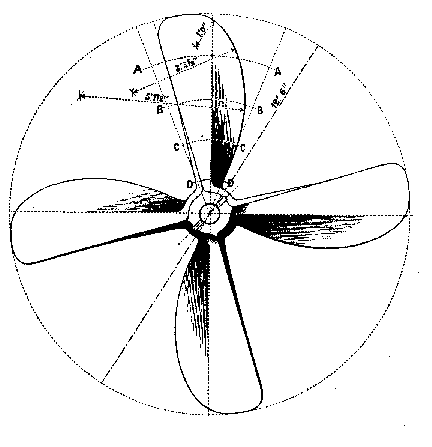
Fig 139.-Screw-Propeller.
is globular and very large. The blades are secured to the hub by flanges,and are bolted on in such a manner that their position may be changed slightlyif desired. The blades are shaped like the section of a pear, the widerpart being nearest the hub, and the blades tapering rapidly toward theirextremities. A usual form is intermediate between the last, and is likethat shown in Fig. 141, the hub being sufficiently enlarged to permit theblades to be attached as in the Griffith screw, but more nearly cylindrical,and the blades having nearly uniform width from end to end.
The pitch of a screw is the distance which would be traversed by the screwin one revolution were it to move through the water without slip; i. e.,it is double the distance C D, Fig. 140. C D' represents the helical pathof the extremity of the blade B, and O E F G H is that of the blade A.The proportion of diameter to the pitch of the screw is determined by thespeed of the vessel. For low speed the pitch may be as small as 1.25 thediameter. For vessels of high speed the pitch is frequently double the

Fig. 140. Tugboat Screw. Fig. 141.-Hirsch Screw.
diameter. The diameter of the screw is made as great as possible, sincethe slip decreases with the increase of the area of screw-disk. Its lengthis usually about one-sixth of the diameter. A greater length produces lossby increase of surface causing too great friction, while a shorter screwdoes not fully utilize the resisting power of the cylinder of water withinwhich it works, and increased slip causes waste of power. An empiricalvalue for the probable slip in vessels of good shape, which is closelyapproximate usually, is S = 4(M/A), in which S is the slip per cent., andM and A are thc areas of the midship section and of the screwdisk in squarefeet.
The most effective screws have slightly greater pitch at the peripherythan at the hub, and an increasing pitch from the forward to the rear partof the screw. The latter method of increasing pitch is more generally adoptedalone. The thrust of the screw is the pressure which it exerts in drivingthe vessel forward. In well-formed vessels, with good screw, about two-thirdsof the power applied to the screw is utilized in propulsion, the remaindlerbeing wasted in slip and other useless work. Its efficiency is in sucha case, therefore, 66 percent. Twin screws, one on each side of the stern-post,are sometimes used in vessels of light draught and considerable breadth,whereby decreased slip is secured.
As has already been stated, the introduction of the compound engine hasbeen attempted, but with less success than in Europe, by several Americanengineers.
The most radical change in the methods of ship-propulsion which has beensuccessfully introduced in some localities has been the adoption of a systemof "wire-rope tow age." It is only well adapted for cases inwhich the steamer traverses the same line constantly, moving backward andforward between certain points, and is never comelled to deviate to anyconsiderable extent from the path selected. A similar system is in usein Canada, but it has not yet come into use in the United States, notwithstandingthe fact that, wherever its adoption is practicable, it has a marked superiorityin economy over the usual methods of propulsion. With chain or rope tractionthere is no loss by slip or oblique action, as in both screw and paddle-wheelpropulsion. In the latter methods these losses amount to an important fractionof the total power; they rarely, if ever, fall below a total of 25 pereent., and probably in towage exceed 50 per cent. The objection to theadoption of chain-propulsion, as it is also often called, is the necessityof following closely the line along which the chain or the rope is laid.There is, however, much less difficulty than would be anticipated in followinga sinuous route or in avoiding obstacles in the channel or passing othervessels. The system is particularly well adapted for use on canals.
The steam-boilers in use in the later and best marine engineering practiceare of various forms, but the standard types are few in number. That usedon river-steamers in the United States has already been described.
Fig. 142 is a type of marine tubular boiler which is in most extensiveuse in sea-going steamers for moderate pressure, and particularly for navalvessels. Here the gases
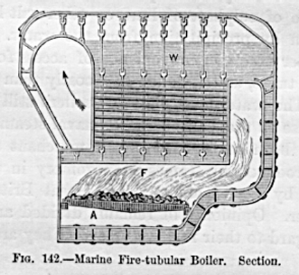
Fig. 142.-Marine Fire-tubular Boiler. Section.
pass directly into the back connection from the fire, and thence forwardagain, through horizontal tubes, to the front connection and up the chimney.In naval vessels the steam-chimney is omitted, as it is there necessaryto keep all parts of the boiler as far below the water-line as possible.Steam is taken from the boiler by pipes which are carried from end to endof the steam-space, near the top of the boiler, the steam entering thesepipes through small holes drilled on the other side. Steam is thus takenfrom the boiler " wet," but no large quantity of water can usuallybe " cntrained " by the steam.
A marine boiler has been quite extensively introduced into the United Statesnavy, in which the gases are led from the back connection through a tube-boxaround and among a set of upright water-tubes, which are filled with water,circulation taking place freely from the water-space immediately abovethe crown-sheet of the furnace up through these tubes into the water-spaceabove them. These " water-tubular " boilers have a slight advantageover the "fire-tubular" boilers already described in compactness,in steaming capacity, and in economical efficiency. They have a very markedadvantage in the facility with which the tubes may be scraped or freedfrom the deposit when a scale of sulphate of lime or other salt has formedwithin them by precipitation from the water. The fire tubular boiler excelsin convenience of access for plugging up leaking tubes, and is much lesscostly than the water tubular. The water-tube class of boilers still remainin extensive use in the United States naval steamers. They have never beenmuch used in the merchant service, although introduced by James Montgomeryin the United States and by Lord Dundonald in Great Britain twenty yearsearlier. Opinion still remains divided among engineers in regard to theirrelative value. They are gradually
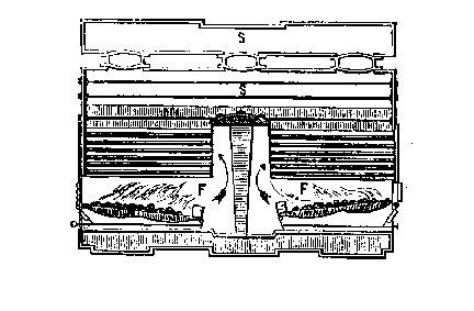
Fig. 143.-Marine High-Pressure Boiler. Section.
reassuming prominence by their introduction in the modified form ofsectional boilers.
Marine boilers are now usually given the form shown in section in Fig.143. This form of boiler is adopted where steam-pressures of 60 poundsand upward are carried, as in steam-vessels supplied with compound engines,cylindrical forms being considered the best with high pressures. The largecylindrical flues, therefore, form the furnaces as shown in the transversesectional view. The gases rise, as shown in the longitudinal section, throughthe connection, and pass back to the end of the boiler through the tubes,and thence, instead of entering a steam-chimney, they are conducted bya smoke-connection, not shown in the sketch, to the smoke funnel or stack.In merchant-steamers, a steam-drum is often mounted horizontally abovethe boiler. In other cases a separator is attached to the steam-pipe betweenboilers and engines. This usually consists of an iron tank, divided bya vertical partition extending from the top nearly to the bottom. The steam,entering the top at one side of this partition, passes underneath it, andup to the top on the opposite side, where it issues into a steam-pipe leadingdirectly to the engine. The sudden reversal of its course at the bottomcauses it to leave the suspended water in the bottom of the separator,whence it is drained off by pipes.
The most interesting illustrations of recent practice in marine engineeringand naval architecture are found in the steamers which are now seen ontransoceanic routes for the merehant service, and, in the naval service,in the enormous iron-clads which have been built in Great Britain.
The City of Peking is one of the finest examples of American practice.This vessel was constructed for the Pacific Mail Company. The hull is 423feet long, of 48 feet beam, and 38.5 feet deep. Accommodations are furnishedfor 150 cabin and 1,800 steerage passengers, and the coalbunkers "stow"1,500 tons of coal. The iron plates of which the sides and bottom are madeare from .5 to one inch in thickness. The weight of iron used in constructionwas about 5,500,000 pounds. The machinery weighed nearly 2,000,000 pounds,with spare gear and accessory apparatus. The engines are compound, withtwo steam-cylinders of 51 inches and two of 88 inches diameter, and a strokeof piston of 4.5 feet. The condensing water is sent through the surface-condensersby circulating-pumps driven by their own engines. Ten boilers furnish steamto these engines, each having a diameter of 13 feet, a length of 13.5 feet,and a thickness of "shell" of .75 inch. Each has three furnaces,and contains 204 tubes of an outside diameter of 3.25 inches. All together,they have 520 square feet of grate-surface and 17,000 square feet of heating-surface.The area of cooling-surface in the condensers is 10,000 square feet. Themachinery is proportioned to develop 4,000 horsepower at 55 revolutionsper minute, with steam of 60 pounds pressure, expanding down to 10 poundsbefore being exhausted into the condenser. The screw has been already illustrated(Fig. 141). It is four-bladed, 20.25 feet in diameter and has a pitch of30 feet. This steamer has made 15.8 knots per hour, equal to 19 statutemiles, and burns from 40 to 80 tons of coal per day, according to the speedand the state of the weather.
The most successful steam-vessels in general use are these screw-steamersof transoceanic lines. Those of the transatlantic lines, usually, are from350 to 450 foot long, generally propelled from 12 to 15 knots (14 to 17.5miles) an hour by engines of from 3,000 to 4,000 horse-power; consumingfrom 70 to 100 tons of coal a day, and crossing the Atlantic in from eightto ten days. These vessels are now invariably fitted with the compoundengine and surface-condensers. One of these vessels, the Germanic, hasbeen reported at Sandy Hook, the entrance to New York Harbor, in 7 days11 hours37 minutes from Queenstown a distance, as measured by thelog and by observation, of 2,830 miles. Another steamer, the Britannic,has crossed the Atlantic in 7 days 10 hours and 53 minutes. These vesselsare of 5,000 tons harden, of 750 " nominal " horsepower (probably5,000 actual).
The modern steamship is as wonderful an illustration of ingenuity and skillin all interior arrangements as in size, power, and speed. The size ofsea-going steamers has become
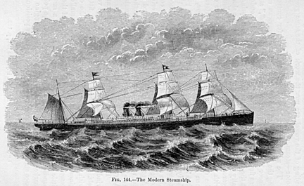
Fig. 144.-The Modern Steamship.
so great that it is unsafe to intrust the raising of the anchor or thesteering of the vessel to manual power and skill; and these operations,as well as the loading and unloading of the vessel, are now the work ofthe same great motor steam.
The now common form of auxiliary engine for controlling the helm is oneof the inventions of the American engineer F. E. Sickels, who devised the"Sickels cut-off," and was first invented about 1850. It wasexhibited at London at the International Exhibition of 1851. It consists1principally of two cylinders working at right angles upon a shaft gearedinto a large wheel fastened by a friction-plate lined with wood, and setby a screw to any desired pressure on the steering-apparatus. The wheelturned by the steersman is connected with the valve-gear of the cylinders,so that the steam, or other motor, will move the rudder preeisely as thehelmsman moves the wheel adjusting the steam-valves. This wheel thus becomesthe steering-wheel. The apparatus is usually so arranged that it may beconnected or disconnected in an instant, and hand-steering adopted if thesmoothness of the sea and the low speed of the vessel make it desirableor convenient. This methodwas first adopted in the United States on thesteamship Augusta.
The same inventor and others have contrived "steam-windlasses,"some of which are in general use on large vessels. The machinery of thesevessels is also often fitted with a steam " reversing-gear,"by means of which the engines are as easily maneuvered as are those ofthe smallest vessels, to which hand-gear is always fitted. In one of theselittle auxiliary engines, as devised by the author, a small handle beingadjusted to a marked position, as to the point marked " stop "on an index-plate, the auxiliary engine at once starts, throws the valve-gearinto the proper position
l "Official Catalogue" l862, vol. iv., Classviii., p.123.
as, if a link-motion, into "middle-gear" thus stoppingthe large engines, and then it itself stops. Setting the handle so thatits pointer shall point to " ahead," the little engine startsagain, sets the link in position to go ahead, thus starting the large engines,and again stops itself. If set at "back," the same series ofoperations occurs, leaving the main engines backing and the little "reversingengine" stopped. A number of forms of reversing engine are in use,each adapted to some one type of engine.
The hull of the transatlantic steamer is now always of iron, and is dividedinto a number of " compartments," each of which is water-tightand separated from the adjacent compartments by iron " bulkheads,"in which are fitted doors which, when closed, are also water-tight. Insome eases these doors close automatically when the water rises in thevessel, thus confining it to the leaking portion.
Thus we have already seen a change in transoceanic lines from steamerslike the Great Western (1837), 2l2 feet in length, of 35.5 feet beam, and23 feet depth, driven by engines of 450 horse-power, and requiring 15 daysto cross the Atlantic, to steamships over 450 feet long, 4.5 feet beam,and 35 feet deep, with engines of 5,000 horse-power, crossing the Atlanticin 7.5 days; iron substituted for wood in construction, the cost of fuelreduced one-half, and the speed raised from 8 to 15 knots and over. Inthe earlier days of steamships they were given a proportion of length tobreadth of from 5 to 6 to 1; in forty years the proportion increased until11 to 1 was reached.
The whole naval establishment of every country has been greatly modifiedby the recent changes in methods of attack and defense; but the severalclasses of ships which still form the naval marine are all as dependentupon their steam-machinery as ever.
It is only recently that the attempt seems to have been made to determinea classification of war-vessels and to plan a naval establishment whichshall be likely to meet fully the requirements of the immediate future.It has hitherto been customary simply to make each ship a little stronger,faster, or more powerful to resist or to make
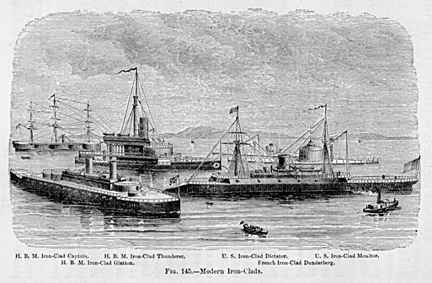
Fig. 145.-Modern Iron-Clads.
attack than was the last. The fact that the direction of progress innaval science and architecture is plainly perceivable, and that upon itsstudy may be based a fair estimate of the character and relative distributionof several classes of vessels, seems to have been appreciated by very few.
In the year 1870 the writer proposed1 a classification of vessels otherthan torpedo-vessels, which has since been also proposed in a somewhatmodified form by Mr. J. Scott Russell.2 The author then remarked that theincrease so rapidly occurring in weight of ordnance and of armor, and inspeed of war-vessels, would probably soon compel a division of the vesselsof every navy into three classes of ships, exclusive of torpedo-vessels,one for general service in time of peace, the others for use only in timeof war.
"The first class may consist of unarmored vessels of moderate size,fair speed under steam, armed with a few tolerably heavy guns, and carryingfull sail-power.
"The second class may be vessels of great speed under steam, unarmored,carrying light batteries and as great spread of canvas as can readily begiven them; very much such vessels as the Wompanoag class of our own navywere intended to be calculated expressly to destroy the commerce ofan enemy.
"The third class may consist of ships carrying the heaviest possiblearmor and armament, with strongly-built bows, the most powerful machinerythat can be given them, of large coal-carrying capacity, and unencumberedby sails, everything being made secondary to the one object of obtainingvictory in contending with the most powerful of possible opponents. Suchvessels could never go to sea singly, but would cruise in couples or insquadrons. It seems hardly doubtful that attempts to combine the qualitiesof all classes in a single vessel, as has hitherto been
1 Journal Franklin Institute, 1870. H. B. M. S. Monarch.
2 London Engineering, 1875.
done, will be necessarily given up, although the classification indicatedwill certainly tend largely to restrict naval operations. "
The introduction of the stationary, the floating, and the automatic classesof torpedoes, and of torpedo-vessels, has now become accomplished, andthis element, which it was predicted by Bushnell and by Fulton three-quartersof a century ago would at somc future time become important in warfare,is now well recognized by all nations flow far it may modify future navalestablishments cannot be yet confidently stated, but it seems sufficientlyevident that the attack, by any navy, of stationary defenses protectedby torpedoes is now quite a thing of the past. It may be perlmps lookedupon as exceedingly probable that torpedo ships of very high speed willyet drive all heavily-armored vessels from the ocean, thus completing thehistoric parallel
between the man-in-armor of the middle ages and the armored man-of-warof our own time.l
Of these classes, the third is of most interest, as exhibiting most perfectlythe importance and variety of the work which the steam-engine is made toperform On the later of these vessels, the anchor is raised by a steamanchor hoisting apparatus; the heavier spars and sails are handled bythe aid of a steam-windlass; the helm is controlled by a steerig-engine,and the helmsman, with his little finger, sets in motion a steam-engine,which adjusts the rudder with a power which is unimpeded by wind or sea,and with an exactness that could not be exceeded by the hand-steering gearof a yacht; the guns are loaded by steam, are elevated or depressed, andare given lateral training, by the same power; the turrets in which thegulls are incased are turned, and the guns are whirled toward every pointof the compass, in less time than is required to sponge and reload
1 Vide "Report on Machinery and Manufacturers, etc.,at Vienna," by the author, Washington, 1875.
them; and the ship itself is driven through the water by tile power often thousand horses, at a speed which is only excelled on land by thatof the railroad-train.
The British Minotaur was one of thc earlier iron-clads. The great lengthand consequent difficulty of maneuvering, the defect of speed, and theweakness of armor of these vessels have led to the substitution of farmore effective designs in later constructions. The Minotaur is a fourmastedscrew iron-clad, 400 feet long, of 59 feet beam and 26.5 feet draught ofwater. Her speed at sea is about 12.5 knots, and her engines develop, asa maximum, nearly 6,000 indicated horse-power. Her heaviest armor-platesare but 6 inches in thickness. Her extreme length and her unbalanced ruddermake it difficult to turn rapidly. With eighteen men at the steering-wheeland sixty others on the tackle, the ship, on one occasion, was 7.5 minutesin turning completely around. These long iron-clads were succeeded by theshorter vessels designed by Mr. E. J. Reed, of which the first, the Bellerophon,was of 4,246 tons burden, 300 feet long by 56 feet beam, and 245 feet draught,of the 14-knot speed, with 4,600 horsepower; and having the " balancedrudder " used many years earlier in the United States by Robert L.Stevens,l it can turn in four minutes with eight men at the wheel. Thecost of construction was some $600,000 less than that of the Minotaur.A still later vessel, the Monarch, was constructed on a system quite similarto that known in the United States as the Monitor type, or as a turretediron-clad. This vessel is 330 feet long, 57.5 feet wide, and 36 feet deep,drawing 24.5 feet of water. The total weight of ship and contents is over8,000 tons, and the engines are of over 8,000 horsepower. The armor is6 and 7 inches thick on the hull and 8 inches on the two turrets, overa heavy teak backing. The turrets contain each two 12-inch rifled guns,weighing 25 tons each, and,
l Still in use on the Hoboken ferry boats.
with a charge of 70 pounds of powder, throwing 3 shot of 600 pounds weightwith a velocity of 1,200 feet per second, and giving it a vis viva equivalentto the raising of over 6,100 tons one foot high, and equal to the workof penetrating an iron plate 13.5 inches thick. This immense vessel isdriven by a pair of " single-cylinder " engines having steam-cylindersten feet in diameter and of 43 feet stroke of piston, driving a two-bladedGriffith screw of 23.5 feet
diameter and 26.5 feet pitch, 65 revolutions, at the maximum speedof 14.9 knots, or about 17.5 miles, an hour. To drive these powerful engines,boilers having an aggre gate of about 25,000 square feet (or more thana half acre) of heating-surface are required, with 900 square feet ofgrate-surface. The refrigerating surface in the condensers has an areaof 16,500 square feet over one-third of an aere. The cost of theseengines and boilers was £66,500.
Were all this vast steam-power developed, giving the vessel a speedof 15 knots, the ship, if used as a "ram," would strike an enemyat rest with the tremendous " energy " of 48,000 foot-tons equalto the shock of the projectiles of eight or nine such guns as are carriedby the iron-clad itself, simultaneously discharged upon one spot.
Bnt even this great vessel is less forrmidable than later vessels. Oneof the latter, the Inflexible, is a shorter but wider and deeper ship thanthe Monarch, measuring 320 feet long, 75 feet beam, and 25 draught, displacingover 10,000 tons. The great rifles carried by this vessel weigh 81 tonseach, throwing shot weighing a half-ton from behind iron-plating two feetin thickness. The steam-engines are of about the same power as those ofthe Monarch, and give this enormous hull a speed of 14 knots an hour.
The navy of the United States does not to-day possess iron-clads of powereven approximating that of either of several classes of British and otherforeign naval vessels.
The largest vessel of any class yet constructed is the Great Eastern (Fig.146), begun in 1854 and completed in 1859, by T. Scott Russell, on theThames, England. This ship is 680 feet long, 83 feet wide, 58 feet deep,28 feet draught, and of 24,000 tons measurement. There are four paddleand four screw engines, the former having steam-cylinders 74 inches indiameter, with 14 feet stroke, the latter 84 inches in
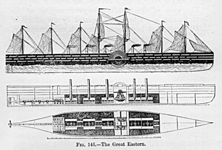
Fig. 146. -The Great Eastern.
diameter and 4 feet stroke. They are collectively of 10,000 actual horse-power.The paddle-wheels are 56 feet in diameter, the screw 21 feet. The steam-boilerssupplying the paddle-engilles have 44,000 square feet (more than an acre)of heating-surface. The boilers supplying the screw-engincs are stilllarger. At 30 feet draughts this great vessel displaces 27,000 tons. Theengines were designed to develop 10,000 horse-power, driving the ship atthe rate of 16.5 statute miles an hour.
The figures quoted in the descriptions of these great steamships do notenable the non-professional reader to form a conception of the wonderfulpower which is concentrated within so small a space as is occupied by theirsteam-machinery. The " horse-power " of the engines is that determinedby James Watt as the maximum obtainable for eight hours a day from thestrongest London draught-horses. The ordinary average draugut-horse wouldhardly be able to exert two-thirds as much during the eight hours' steadywork of a working-day. The working-day of the steam-engille, on the otherhand, is twenty-four hours in length.
The work of the 10,000 horse-power engines of the Great Eastern could bebarely equaled by the efforts of 15,000 horses; but to continue their workuninterruptedly,
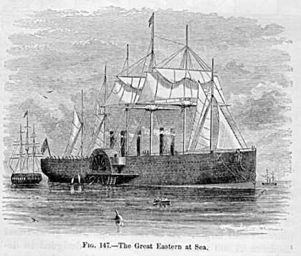
Fig. 147. The Great Eastern at Sea.
day in and day out, for weeks together, as when done by steam, wouldrequire at least three relays, or 45,000 horses. Such a stud would weigh20,000 tons and if harnessed "tandem" would extend thirty miles.It is only by such a comparison that the mind can begin to comprehend theutter impossibility of accomplishing by means of animal power the worknow done for the world by steam. The cost of the greater power is but aboutone-tenth that of horse-power, and by its means tasks are accomplishedwith ease which are absolutely impossible of accomplishment by animal power.
It is estimated that the total steam-power of the world is about 15,000,000horse-power, and that, were horses actually employed to do the work whichthese engines would be capable of doing were they kept constantly in operation,the number required would exceed 60,000,000.
Thus, from the small beginnings of the Comte d'Auxiron and the Marquisde Jouffroy in France, of Symmington in Great Britain, and of Henry, Ramsey,and Fitch, and of Fulton and Stevens, in the United States, steam-navigationhas grown into a great and inestimable aid and blessing to mankind.
We to-day cross the ocean with less risk, and transport ourselves and ourgoods at as little cost in either time or money as, at the beginning ofthe century, our parents experienecd in traveling one-tenth the distance.
It is largely in consequence of this ingenious application of a power thatreminds one of the fabled genii of Eastern romance, that the mechanic andthe laborer of to-day enjoy comforts and luxuries that were denied to wealth,and to royalty itself, a century ago.
The magnitude of our modern steamships excites the wonder and admirationof even the people of our own time; and there is certainly no creationof art that can be grander in appearance than a transatlantic steamer ahundred and fifty yards in length, and weighings with her stores, fiveor six thousand tons, as she starts on her voyage, moved by engines equalin power to the united strength of thousands of horses; none ean more fullyawaken a feeling of awe than an immense structure like the great moderniron-clads (Fig. 145), vessels having a total weight of 8,000 to lO,000tons, and propelled by steam-engines of as many horsepower, carrying gunswhose shot penetrate solid iron 20 inches thick, and having a power ofimpact, when steaming at moderate speed, sufficient to raise 35,000 tonsa foot high.
Far more huge than the Monarch among the iron-clads even is that prematurely-builtmonster, the Great Eastern (Fig. 147), already deseribed, an eighth ofa mile long, and with steam doing the work of a stud of 45,000 horses.
Thus we are to-day witnessing the literal fulfillment of the predictionsof Oliver Evans and of John Stevens, and almost that contained in the coupletswritten by the poet Darwin, who, more than a century ago, before wven theearliest of Watt's improvements had become generally known, sang:
"Soon shall thy arm, unconquered Steam, afar Drag the slow barge,or drive the rapid car; Or, on wide-waving wings expanded, bear The flyingchariot through the fields of air."