The siphons used in conflagrations are made as follows. Take two vessels of bronze, A B C D, E F G H, (fig. 27),
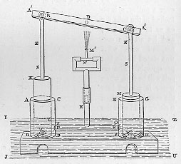 having the inner surface bored
in a lathe to fit a piston, (like the barrels of water-organs), K L, M N
being the pistons fitted to the boxes. Let the cylinders communicate
with each other by means of the tube X 0 D F, and be provided with
valves, P, R, such as have been explained above, within the tube X 0 D F
and opening outwards from the cylinders. In the bases of the cylinders
pierce circular apertures, S, T, covered with polished hemispherical
cups, V Q, W, Y, through which insert spindles soldered to, or in some
way connected with, the bases of the cylinders, and provided with
shoulders at the extremities that the cups may not be forced off the
spindles. To the centre of the pistons fasten the vertical rods S E, S
E, and attach to these the beam A' A', working, at its centre, about the
stationary pin D, and about the pins B, C, at the rods S E, S E. Let
the vertical tube S' E' communicate with the tube X 0 D F, branching
into two arms at S', and provided with small pipes through which to
force up water, such as were explained above in the description of the
machine for producing a water-jet by means of the compressed air. Now,
if the cylinders, provided with these additions, be plunged into a
vessel containing water, I J U Z, and the beam A' A' be made to work at
its extremities A', A', which move alternately about the pin D, the
pistons, as they descend, will drive out the water through the tube E'
S' and the revolving mouth M'. For when the piston M N ascends it opens
the aperture T, as the cup W Y rises, and shuts the valve R; but when it
descends it shuts T and opens R, through which the water is driven and
forced upwards. The action of the other piston, K L, is the same. Now
the small pipe M', which waves backward and forward, ejects the water to
the required height but not in the required direction, unless the whole
machine be turned round; which on urgent occasions is a tedious and
difficult process. In order, therefore, that the water may be ejected
to the spot required, let the tube E' S' consist of two tubes, fitting
closely together lengthwise, of which one must be attached to the tube X
0 D F, and the other to the part from which the arms branch off at S';
and thus, if the upper tube be turned round, by the inclination of the
mouthpiece M' the stream of water can be forced to any spot we please.
The upper joint of the double tube must be secured to the lower, to
prevent its being forced from the machine by the violence of the water.
This may be effected by holdfasts in the shape of the letter L, soldered
to the upper tube, and sliding on a ring which encircles the lower.
having the inner surface bored
in a lathe to fit a piston, (like the barrels of water-organs), K L, M N
being the pistons fitted to the boxes. Let the cylinders communicate
with each other by means of the tube X 0 D F, and be provided with
valves, P, R, such as have been explained above, within the tube X 0 D F
and opening outwards from the cylinders. In the bases of the cylinders
pierce circular apertures, S, T, covered with polished hemispherical
cups, V Q, W, Y, through which insert spindles soldered to, or in some
way connected with, the bases of the cylinders, and provided with
shoulders at the extremities that the cups may not be forced off the
spindles. To the centre of the pistons fasten the vertical rods S E, S
E, and attach to these the beam A' A', working, at its centre, about the
stationary pin D, and about the pins B, C, at the rods S E, S E. Let
the vertical tube S' E' communicate with the tube X 0 D F, branching
into two arms at S', and provided with small pipes through which to
force up water, such as were explained above in the description of the
machine for producing a water-jet by means of the compressed air. Now,
if the cylinders, provided with these additions, be plunged into a
vessel containing water, I J U Z, and the beam A' A' be made to work at
its extremities A', A', which move alternately about the pin D, the
pistons, as they descend, will drive out the water through the tube E'
S' and the revolving mouth M'. For when the piston M N ascends it opens
the aperture T, as the cup W Y rises, and shuts the valve R; but when it
descends it shuts T and opens R, through which the water is driven and
forced upwards. The action of the other piston, K L, is the same. Now
the small pipe M', which waves backward and forward, ejects the water to
the required height but not in the required direction, unless the whole
machine be turned round; which on urgent occasions is a tedious and
difficult process. In order, therefore, that the water may be ejected
to the spot required, let the tube E' S' consist of two tubes, fitting
closely together lengthwise, of which one must be attached to the tube X
0 D F, and the other to the part from which the arms branch off at S';
and thus, if the upper tube be turned round, by the inclination of the
mouthpiece M' the stream of water can be forced to any spot we please.
The upper joint of the double tube must be secured to the lower, to
prevent its being forced from the machine by the violence of the water.
This may be effected by holdfasts in the shape of the letter L, soldered
to the upper tube, and sliding on a ring which encircles the lower.